
By Jeff Wright – GBI Vice President of Technical Services
Before starting on your next fiberglass repair or boat modification, let’s look at some projects that would most-likely require you to make appropriate structural reinforcements to your boat. After all – boats are complicated structures. Sailboats endure multiple loads from the rigging as the shrouds are pulled in tension and the mast is compressed into the hull. Inboard-powered boats must transfer the thrust from the engine mounts into the stringers while outboard and sterndrive boats place substantial loads on the transom. Even the steering wheel at a stand-up helm can undergo high loads when the boat moves fast through large waves — the security of which many go-fast boaters may take for granted. Let’s dive in.
Relocating Thru Hulls
When breathing new life into an old boat with an updated engine, it is very possible that your existing thru hull locations will not work. “Repairing Machined Holes in Fiberglass” in Epoxyworks 21 is a detailed article on this subject. Patching unused holes, particularly those above the waterline, may not require a full repair as described in the WEST SYSTEM® User Manual & Product Guide.
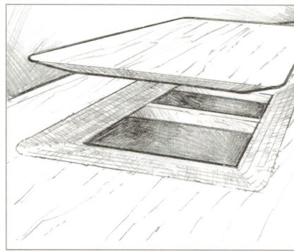
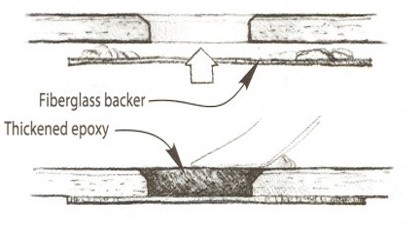
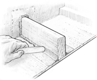
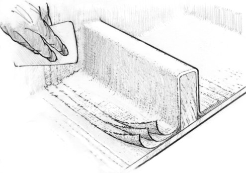
Figure 1 and 2 illustrate approaches to patching unused through holes above the waterline. Note the rounded or chamfered edges in Figure 1.
This reduces the chance of a cosmetic “ring” appearing around the filled hole. Figure 2 shows how you can bevel out even farther to further reduce the chance of a cosmetic issue under high-gloss paints.
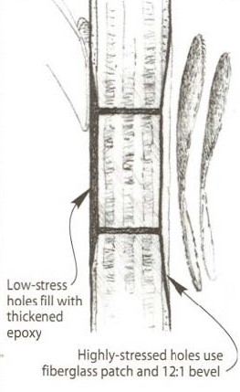
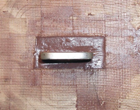
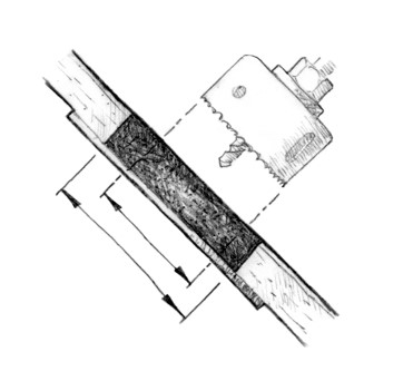
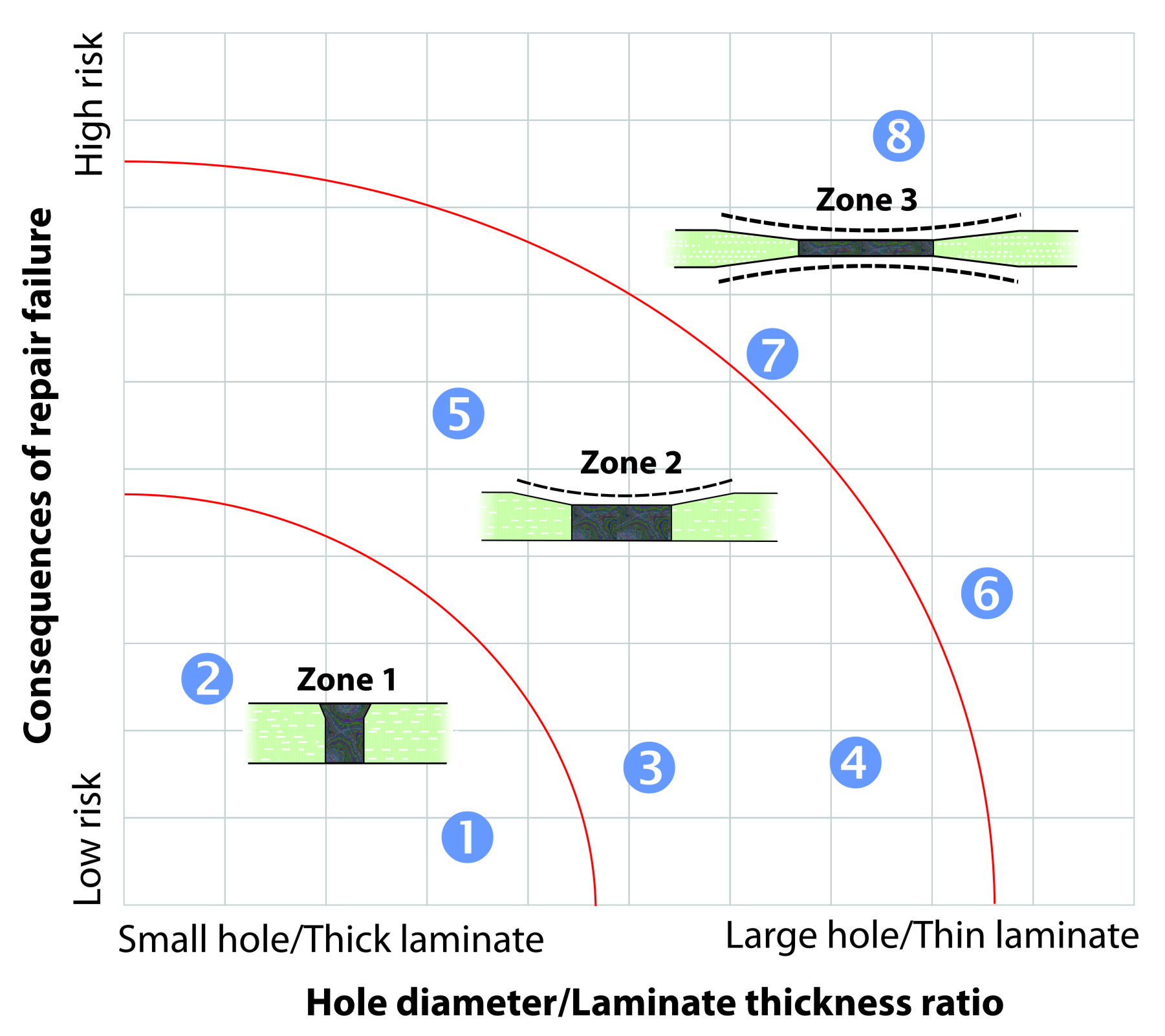
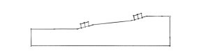
When filling holes under the waterline, use a more conservative approach. If an existing hole can be used but needs to be smaller, you can fill the hole with thickened epoxy and re-drill it to the correct size as seen in Figure 3. Figure 4 is a chart from the previously mentioned article that explains how the consequence of failure and the thickness of the laminate will influence the repair method.
Stringer Changes
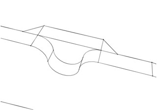
A new inboard engine may not have its engine mounts and vibration isolators located in the same place as the old engine. If the height of the stringer needs to be increased, be sure to add the height in such a way that the stringer has a smooth profile. Abrupt profile changes create stress concentrations and can cause a crack to start. If reducing height, an engineer may need to be involved. The height of the stringer has a major impact on the strength and stiffness of the stringer. Reducing height will require additional fiberglass overlay to maintain the strength and stiffness. Figures 5 and 7 show stringers with smooth profiles that avoid stress concentrations.
Stringer spacing should not change unless an engineer is involved. Increasing the distance between stringers will increase the span of the unsupported hull shell panel resulting in higher deflection and stress. Notching the stringers may be required to avoid changing the spacing.
Figure 6 demonstrates how to address interference with an engine and the stringer by using a tapered block to reinforce the rounded notched area and avoiding moving the stringer. It is also important to understand how the keel loads are transferred into the stringers when working on sailboats. As I mentioned before, consult a naval architect or engineer if you don’t understand the effect of the changes.
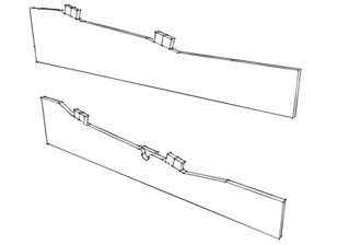
If completely replacing the stringer, review the WEST SYSTEM User Manual & Product Guide for best practices. Using thickened epoxy to create a fillet and staging the tabbing fabric is an improvement over the installation methods used by many production builders. This technique is shown in Figure 8 and 9.
Production boats will often not have the stringer core touching the bottom of hull to avoid a “hard spot.” Bonding the stringer in epoxy with a nice curve on each side will distribute load very well. This technique is used by custom boat builders on a regular basis.
Rigging Changes
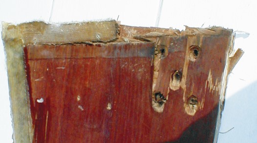
Moving or replacing chainplates may require holes in new locations or expose deteriorated plywood. Oversized or deteriorated holes can be filled with thickened epoxy and re-drilled. Rotted plywood (Figure 10) should be addressed by scarfing in a new piece (Figure 11).
Take advantage of the removed hardware. Encapsulate the core material around any deck penetrations with epoxy (Figure 12). The constant flexing and potential sealant failure can expose the core to water over the life the boat. The thickened epoxy will protect the core for the life of the boat.
If installing new backing plates, aluminum plates should never be installed in the laminate the way plywood is often used. If any moisture, particularly saltwater, contacts the plate (and it corrodes), it will expand and blow apart the laminate. Aluminum plates should always be outside of the laminate.
Changes to the Helm
Instrumentation for engines has advanced significantly. Multiple gauges can be replaced by a single touch screen. On the other hand, what used to be small bracket-mounted electronics have become very large flush-mounted screens. Both of these upgrades can require major changes to a helm station. Figure 13 illustrates how significant these changes can be.
When filling holes on a helm station, it is critical to use a good backing surface to laminate against. Since these surfaces are often flat, consider laminating from the backside with your temporary form/lamination surface attached to the finished/outside surface of the helm. This is another situation where all edges should be chamfered to reduce the risk of “lines” appearing after paint is applied. It is common for the reinforcing plywood to be ¾” thick in instrument areas. Because so much of the area is cutaway for the instruments, the strength can be greatly reduced requiring a thick laminate for the material that is left to support everything. Keep in mind, as I mentioned in the opening, grab handles and steering wheels need to have a secure base if making changes in those areas.
Transoms
The current trend of repowering obsolete sterndrive boats with modern outboards requires critical attention to the structure of the boat. With all of the thrust and weight of the engines supported by the transom, it is without a doubt considered a highly loaded area. It is important to consider both the strength of the transom and the attachment to the boat.
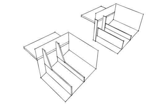
Figure 14 illustrates how the gussets in both cases stiffen the transom, but the example in the forefront securely attaches the transom to the stinger and distributes the loads. The image in back would have a very stiff transom but would flex away from the hull. It is import that the entire load is evenly distributed into the hull to prevent the transom from excessive flexing.
The core material in the transom is often a high-strength material such as marine-grade plywood. It is important to use a strong material. Some people are resistant to using plywood for fear of rot weakening the transom. We believe a properly laminated transom, with care taken to epoxy-seal all penetrations, will last the life of the boat. Unfortunately, the addition of hardware such as transducers, or not resealing holes as a maintenance task, can greatly reduce the life of the plywood. Even with proper maintenance, we still recommend taking the time to epoxy-seal all of the penetrations. Water inside of any laminate can cause damage, especially when exposed to freeze/thaw cycles.
Act Locally, Think Globally
This article is a just a brief review of how to address structural changes to your boat. Remember that even though a modification may be as simple as relocating a winch or an engine mount, it is important to understand where the load is being transferred into the boat’s structure. Was a winch located over a bulkhead that prevented the deck from flexing? Is the stringer made of a low-density core while the original motor mount area had a high-density insert? Should a high-density insert be installed in the new location for secure fastening? Involving an expert is a good idea when changes may affect the integrity of the boat.