Stitch & Glue Details
Spring 1994

GET STARTED
FREE PRINT & DIGITAL EDITIONS
Spring 1994
by Captain James R. Watson
You may have read my articles about how to build mail boxes, canoe paddles, wheels, tillers, how to get glue off clothing and so on. Somebody called the other day and asked, “You ever build a boat?” Well, it so happens I’m building one right now and it’s a good example for describing the latest stitch and glue techniques.
Actually, I’m building new hulls to retrofit my Hobie 14. She’s 20 years old now and the hulls are nearly worn through from all the dragging over the sand beach. Over the years, I have wished for lighter hulls to pull onto the beach and ones that would better carry the weight of a passenger. Naturally, I wanted a faster boat, so I’m building lightweight 18′ hulls that I will attach to my H-14 components; crossbeams, trampoline, rudders, mast and sail. I chose the developed plywood method of construction—stitch and glue.
Developed plywood construction is an excellent method of hull construction. With this method, you can produce very lightweight, strong hulls. It eliminates lofting, setting up and laminating, so a boat can be built in relatively few work hours. A very thorough description of this building technique can be found in Chapter 23 of The Gougeon Brothers on Boat Construction.
In this construction method, plywood panels that become the hull are first cut to a designed shape. Second, they are temporarily joined so the two panels can be opened like a book. The panels are then bonded permanently to a specific angle.
With some designs, plywood is compounded or tortured, bent in two directions at once and forced into shape. Stitch and glue panels are bent in one plane and joined. Rigidity is gained by the joined panels meeting at an angle.
The common way to temporarily join the panels is with copper wire passed through drilled holes and twisted to the desired tension. Copper wire is good but when clipped the remaining wire interferes with shaping the joint with a plane. Extracting the wire solves this problem, but it’s tedious and time consuming. An alternate method is to bond nylon webbing along the joining panel’s edge to create a hinge at the keel. The problem with the webbing is that you cannot draw panels into position. This works great on long, straight developed plywood projects such as our Stresform® mast designs. This method eliminates the tedious task of twisting the wire, which sometimes breaks with excessive twisting.
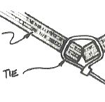
The latest concept is the best yet. I use nylon cable ties (tie wraps) to join the panels. They’re cheaper than copper wire. I bought them from an electrical supply shop but you could probably get them from any home improvement store. For 3 mm to 6 mm thick plywood projects I used 7/8″ x 3-7/8″, drilling a 3/32″ diameter hole. The integral ratchet allows easy, fine, yet positive tightening superior to copper wire or webbing. It can also be easily released by inserting a small pointed tool into the ratchet.
The plastic cable ties cut clean with a sharp chisel and do not interfere with planing. Bonding over the flush plastic does not compromise the structure.
On my catamaran project I used 9 oz., 2″ wide Episize™ fiberglass tape when fabricating the interior (establishing the keel angle) and exterior keel joint. I staggered the glass tape to achieve an aggregate built-up of glass. The multiple, gradual steps reduce the stress concentration and improve the fairing process. When it cured, I sanded the edges with 50-grit sandpaper on a 5″ rubber sanding block to knock off the bumps. I thickened epoxy with 410 Microlight to a peanut butter consistency and applied it with a 5″ wide putty knife and a plastic spreader. When this mixture cures it sands smooth and the glass build-up is undetectable. I then bonded on the shear clamps and folded each hull. A deck jig held the shape of the hull while I installed the sub-level and deck beams.
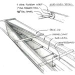
My catamaran is built of 10 pounds-per-sheet, 3 mm-thick okoume, marine grade plywood. It bends fair and produces a beautiful catamaran hull. However the flat sections from the centerboard case forward lacked the degree of panel stiffness I wanted. To solve this, I installed a sub-level. First, I bonded a 1″-wide strip of 3 mm plywood to both sides of the inside of the hull panels 8 inches below the shear clamp. Next, discs of ¼”-thick pine cut with a 1″-diameter hole saw and sawn with a 3/8″-wide slot to the center hole were bonded onto the sub-level strip. I spaced them every 12″. These were held in place with staples until the epoxy cured. Last, I bonded 3/8″-diameter wooden dowels into these discs connecting the two sides in a ladder-type arrangement. The dowels serve as tension/compression struts. This sub-level configuration stiffens the hull enormously with minute weight increase. I continued the sub-level structure back to the centerboard case where the struts run from the hull panels to the case sides. This helps dump the loads exerted from the centerboard into the hull.
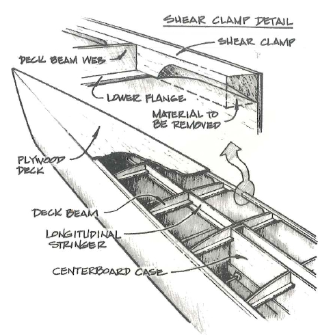
An excellent place to trim excess pounds off a craft is at the shear clamp. A triangular cross section yields maximum bonding area to the hull sides and the deck for the least weight. In addition to saving weight, a lightweight shear clamp—one with limited cross sectional mass—minimizes potential dimensional change via expansion and contraction. A large difference in the thickness of the materials on each side of the joint may impose significant stress concentrations from loads created by expansion and contraction. The more material (in section) the more net dimensional movement may occur. Excessive expansion and contraction can result in tension failure (a split) at the corner of the shear.
However, during the process of building compounded plywood hulls, a large shear clamp offers an advantage. A flimsy shear will buckle in compression during the folding process, and you will not be able to achieve the degree of compounding desired. Also, a heavy shear helps support the lateral loads that ropes or straps (used in the folding process) impose on the panels in that area. On my catamaran hulls, I used a whopping 1″ x 1″ piece of timber for the shear clamp. It served me well, staying steady and true when I folded the thin plywood into shape.
When it came time to install the “I-beam” shaped deck beams, I was happy to have the square clamps. I bonded 1″-wide plywood strips, that act as the bottom flanges of the I-beam, to the flat underside of the clamp. After all the good they offered to this point, I wanted to shave some weight off the immense shear clamps by removing a triangular section from the lower inside corner of the clamp. The width of the hull is only 12″ maximum so there was no way I could get a router in there. Instead I used a 2″ diameter Stanley drum cutter mounted in a drill motor. At each side of the deck beams I first cut diagonally from a half-inch below the upper, inside corner to the intersection at the hull panel. Then I lopped of all that extra material with a chisel. After grinding with the drum cutter and a little sanding, I had a nice triangular shear clamp.
To complete the deck beams, I cut the top of the lightweight webs to the crown shape off a template which was established using a deck crown tram. I simply butted these webs between the shear clamps and bonded them to the clamps and lower flange with epoxy thickened with 406 Colloidal Silica. A center, discontinuous stringer acting as a longitudinal web was then butted between the beam webs, resting on the lower flange strips. The structure was very close to fair but a light sanding with a 24″-long sanding block with 50-grit paper trues things up fast. For ultimate rigidity on the fore deck, where kids like to sit when sailing, I bonded a continuous longitudinal stringer to the bottom of the deck beams and longitudinal webs, which were notched to be flush with the bottom of the deck beam flanges. This method of construction creates a very lightweight, extremely rigid structure.
My catamaran is completely decked and the only openings are provided by two screw-in plastic inspection plates. They have O-rings which make them perfectly watertight. If the hulls get water in them, I can simply reach through the hatch and sponge them dry. This is a good practice.
However, airtight hulls do pose a problem. Air inside the hull will expand and contract with temperature changes. When trailering the boat over hills, increases in altitude can create a dramatic pressure difference between the inside and outside of the hull. These differences exert even, powerful pressure on the exterior panels, making them deflect and severely stressing the joints. We have seen joints fail because of high loads created by such conditions.
Venting the hulls prevents this problem. There are many ways to do it: the simplest is to drill a 1/16″-diameter hole in the plastic port. It will be large enough to do the job, and small enough that water won’t enter through it. Another way to vent is to bond a copper tube into the deck structure, bend it over for a snorkel effect, and pinch the end nearly shut to prevent moisture from entering.
I’ll be painting the boat white to prevent excessive heat. When the boat is sitting idle, I’ll remove the inspection plates to keep the interiors ventilated.
The usual way to make a non-skid surface is to add a non-skid compound to the paint system. For this project, however, I am using a flexible non-skid pattern mold. After cutting the shapes you want, thicken epoxy with 406 Colloidal Silica and apply one coat to the intended non-skid area. Lay the non-skid mold pattern into position and squeegee it down. You can lubricate the squeegee by applying liquid dish detergent to the back of the mold. Squeegee all air and excess epoxy from the mold, then clean the excess epoxy away from the edges.
When the epoxy cures, peel off the flexible mold sheet and repeat the process to create a similar pattern on the other hull. Abrade the cured epoxy with an abrasive pad, which will follow the non-skid contour without reducing its profile, then paint all of the non-skid areas to match.
The results of this project are detailed in New Beach Cat Part I and Part II.