Staudacher’s Strongback Table
Spring 2006

GET STARTED
FREE PRINT & DIGITAL EDITIONS
Spring 2006
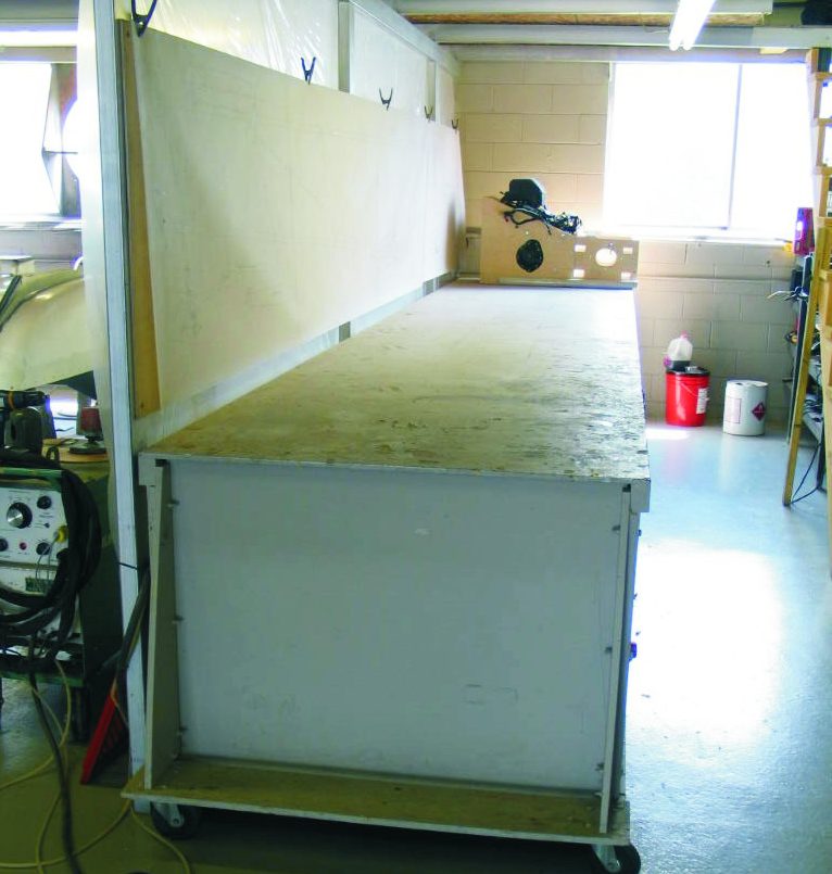
Above: This strongback table is used to assemble airplane wings in John Staudacher’s shop. It must not twist or sag.
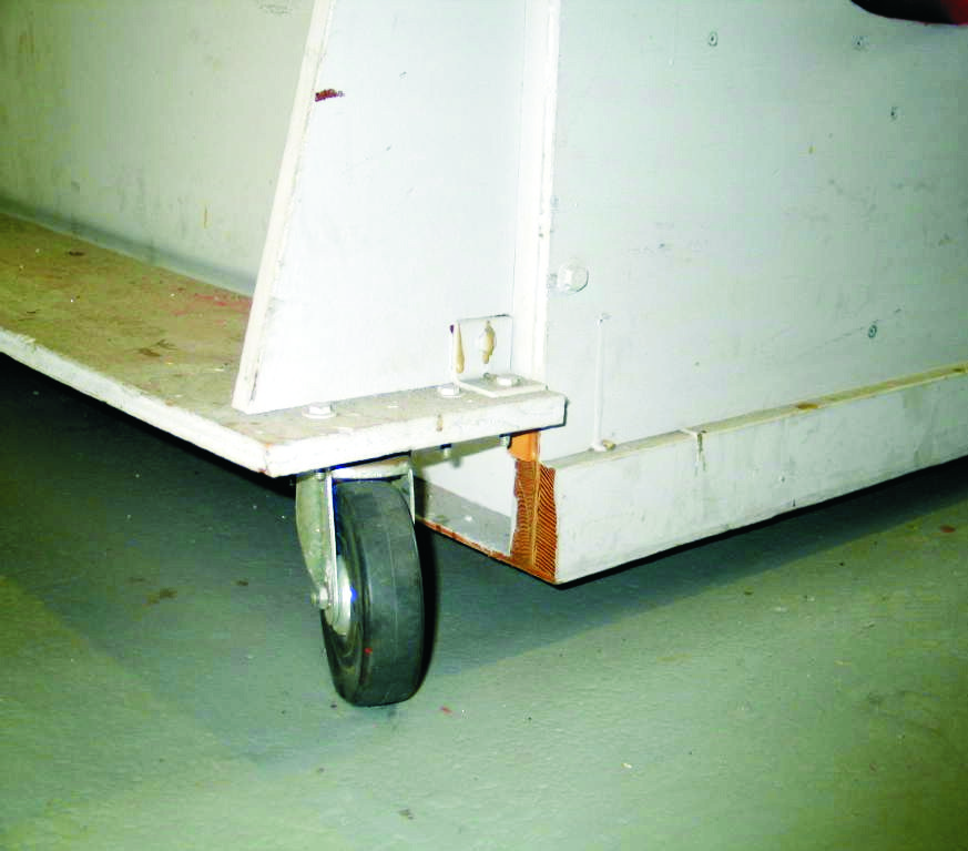
Jon Staudacher, of Staudacher Hydroplanes and Aircraft, has been using a long, very flat, work table/strongback that is mounted on casters. The table was originally 32′ long, but because of space considerations, Jon has since shortened it to 20′ (Photo 1, at top). Four rubber casters support it, one at each corner (Photo 2, below).
Jon uses this table as a surface to assemble airplane wings, so it cannot have twist or sag. Because of its stiffness, the table is not dependent on having an extremely level floor. When the table is moved to a different location, it is easy to shim it level. It is stiff enough that it does not sag, and if there is a little twist, it is easily shimmed out. Since the tabletop is the reference point for all objects being built, the table does not have to be perfectly level, but it must have no twists. If Jon expects to use weights for clamp pressure, as he often does when building the frames for wings, he temporarily shims the bottom rail of the table so it cannot sag under the weight. The table doubles as a strongback with grid lines drawn on the top for locating frames.
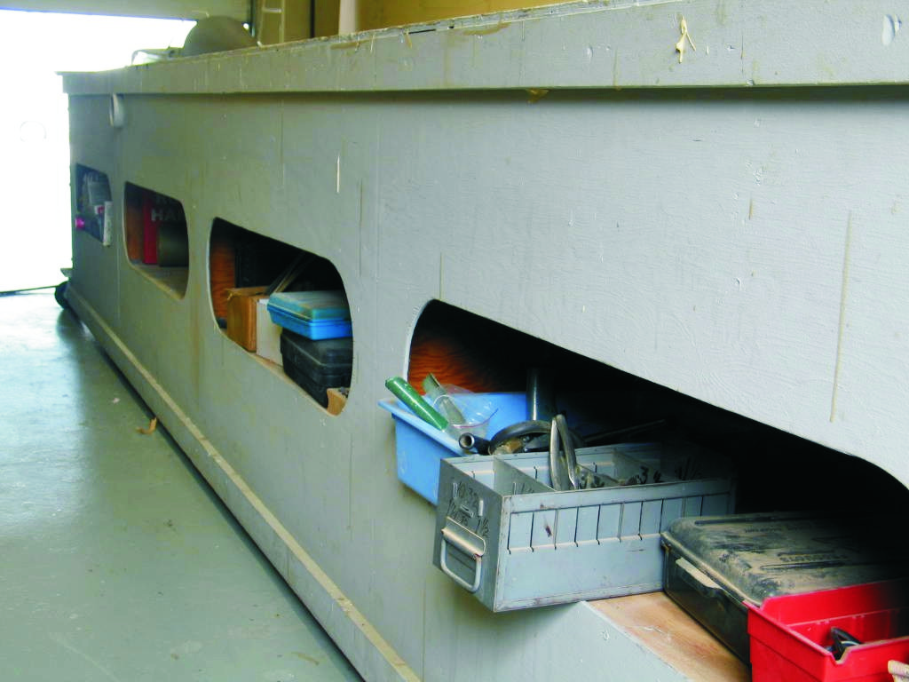
A table like this has to be built carefully, but the materials that go into the construction are very light and readily available. The table is a long box beam made with plywood, and all pieces are glued together to make the table very rigid. There are plywood bulkheads every 4′ to keep the front and back of the table from buckling. In turn, the front and back of the table keep the top flat, without twist. The top is supported on 16″ centers to prevent any drooping of the plywood top between bulkheads. In order not to waste space, storage is built into the front of the table. The access holes are centered between the top and bottom rails, and have oval ends. These are important dimensions. If the access holes were sawn too close to the bottom or top surface, the table would lose its rigidity. Because square corners can cause stress concentrations, the holes have rounded ends (Photo 3).
Full or half sheets of plywood are used where ever possible. Construction starts by sandwiching the top and bottom of the front and back panel between two 1×4s (Photo 4), which were scarfed together to improve straightness. A ¼” plywood bottom panel was glued to the bottom rails. Then ¼” plywood bulkheads and supports for the top were installed. The top was glued to the top of the side rails, bulkheads, and supports. Finally, brackets of scrap OSB were bolted to the ends of the table to support casters (Photo 2).


