

by Brian Knight—GBI Technical Advisor
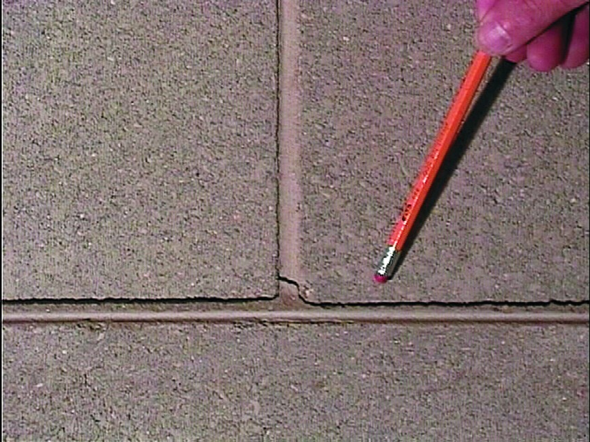
I was in my basement applying some 2×4 furring to a concrete block wall in preparation for insulating and hanging drywall when I noticed a crack in a horizontal mortar joint about halfway between the floor and the ceiling running nearly the length of the wall. This crack was an indication that the block wall was bowing inward. Without knowing how long this had been going on, or how much pressure it took to cause the problem, I realized that I had to take some steps to stop the wall from bowing more.
There are two common methods traditionally used to repair this problem. One is to dig the dirt away from the wall, twist some augers into the surrounding soil, and use tie rods to pull the wall back into place. The other method uses steel I-beams that are installed on the inside of the wall. They are attached to the basement floor and the floor joists to prevent the wall from bowing inward. Properly designed, the I-beams withstand the bending load on the wall. While both methods work, they each have obvious disadvantages, and neither method sounded appealing to me. Digging soil away from the house is not good for my garden, and I was not enthusiastic about having I-beams attached to my basement wall.
My idea on how to stabilize the wall was to use a variation of hardware bonding that Gougeon Brothers has been advocating for years. I bonded a ½” concrete reinforcing bar (rebar) into a slot milled into a 2×4 furring strip. The wood furring would provide a space for insulation and electrical wiring, and also provide a nailing area for the drywall. The steel rebar would provide the tensile strength that the concrete wall was lacking. But my idea would work only if the steel could be bonded to the furring and the furring to the wall.
The theory behind my basement wall fix
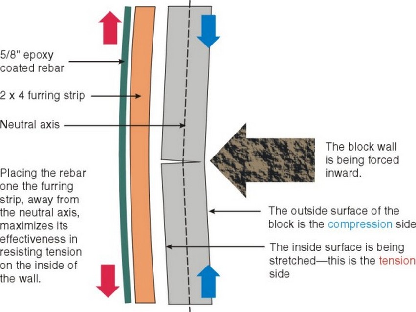
Looking at my concrete block wall, you can see that it is being forced inward. The outside surface of the block is the compression side of the wall. The inside surface is being stretched—this is the tension side of the wall. Concrete has very poor tensile strength, which is why cracks are appearing. The mortar is failing in tension. The goal of my stabilization project is to create a tension member that provides the tensile strength lacking in the concrete.
Bending stresses
My basement wall is bowing inward. The bowing or bending stresses are the result of a combination of forces. If you stand in the middle of a plank supported by two sawhorses, the plank bends under your weight. The top surface of the plank is being compressed. The bottom surface is being stretched, which puts it in tension. The compression load is at its maximum at the top surface of the plank and gradually transitions to a tensile load that is at its maximum on the bottom surface of the plank. At the center of the plank, there is neither compressive load nor tensile load. This is called the neutral axis, and no load is exerted here.
The material furthest from the neutral axis is required to handle more load than the material closer to the neutral axis. Engineers design beams with this in mind. For example, look closely at a laminated wood beam. The wood with the straightest grain and the fewest knots is used in the top and bottom plies of the beam, and the poorer grades of wood with more and larger knots are grouped at the middle of the beam. There is more stress near the surfaces and less stress nearer the neutral axis, so the best quality wood is located where it will do the most good.
Determining Reinforcement Location
When my basement wall was built 30 years ago, a reinforcing rod was installed vertically in the core of the wall every 4 feet or so. Unfortunately, this put the steel at the neutral axis of the wall, not the optimum location for reinforcement.
My fix for the wall, in effect, moves the location of the reinforcing rod from the neutral axis of the wall to a point that maximizes its usefulness as a tension member. The further the steel is from the neutral axis the more effective it is.
Look again at the diagram above. As the steel rebar is bent in the middle of the wall, it tries to become longer (tension). However, it cannot move because the furring/steel rebar assembly is glued to the wall. The tension in the middle of the wall translates into shear (sliding) force, with most of the shear load occurring at the ends of the board. There is very little outward thrust near the ends of the furring since the top and bottom of the wall are anchored to joists and the floor.
Shear Load Testing
To determine how much shear load the wood-to-concrete block joint would take, we made a sample and tested it. The sample shown in the photo (below left) consists of a concrete block with two pieces of 2×4 bonded to it with epoxy (105/206/404). After allowing sufficient time for the epoxy to cure, we loaded the sample in our hydraulic test frame and slid the 2x4s off the concrete block. We recorded the load when the sample failed and calculated the pounds per square inch of effort necessary to break it. The total load exerted on the test sample when it finally broke (below right) was over 30,000 pounds, an astounding 1480 pounds per square inch. This was much higher than any of us here at GBI expected.
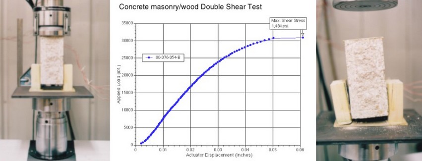
Center | The applied load and the movement of the actuator as it pushes the wood up past the block are recorded until the bond between the materials fails.
Right | The failed sample after 30,000 lb + of force.
This was good news for my repair idea. An 80″ long 2×4 has 280 square inches of glue area. The shear strength of my cement block, as determined by the shear test described above, is 1480 psi. That means that each 80″ furring strip is capable of resisting almost 250,000 lb. of force if the force is evenly distributed. As stated above, the force steadily increases as the distance from the middle increases. Even if you consider just the top and bottom 8″, each furring strip will handle a load pushing out in the center of the 2×4 of 82,880 lb. I have one 2×4 located every 2′ on the wall. That should withstand a lot of pressure.
As mentioned, I have no idea of the load being exerted on the wall. The wall has stood for over 30 years without a catastrophic failure. I know the new furring strips will support an enormous load, and I feel quite confident that I have stabilized the wall. I will monitor the bow in the wall by occasionally standing a straight edge at a given point along the wall and measuring the deflection present. If the wall bulges more, the gap at the ends of the straight edge will increase. If the increase occurs at an alarming rate, I will have to dig outside the wall and stabilize it more conventionally.
Installation method
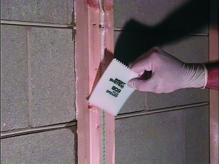
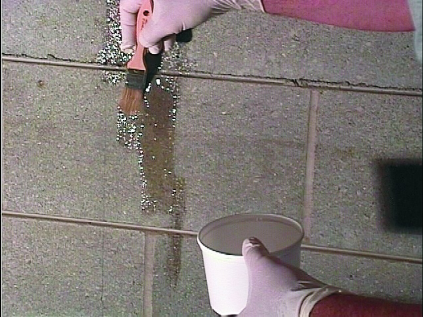
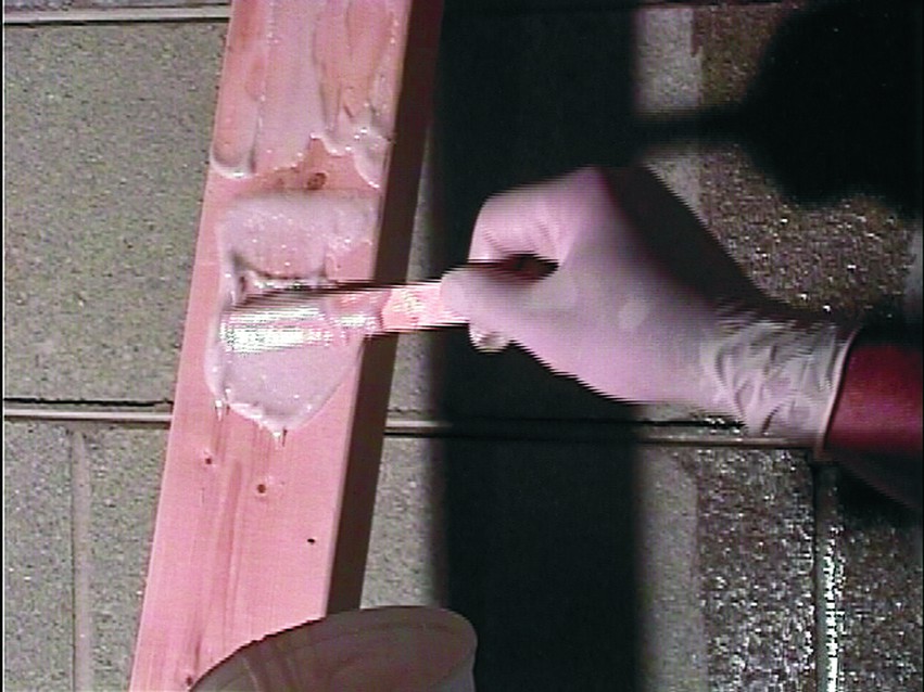
Before installing the 2×4 furring strips, I first prepared the materials by milling a 5/8″ wide x 5/8″ deep slot in the face of each 2×4. Then I pre-fit the 2×4’s drilled holes for Tapcon™ concrete fasteners and removed dust and loose material from the wall. I cleaned and roughed up the epoxy-coated rebar with steel wool. The installation proceeds as follows:
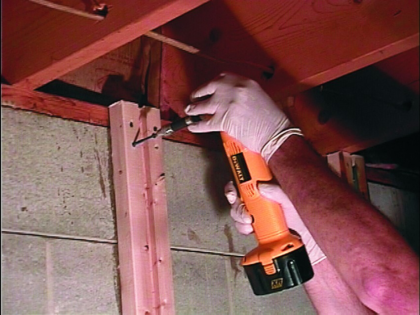
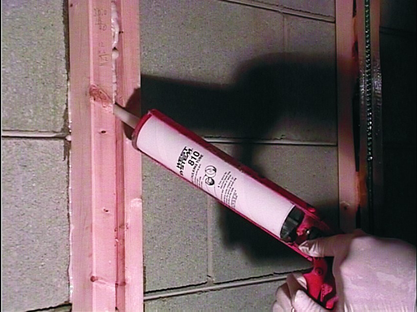
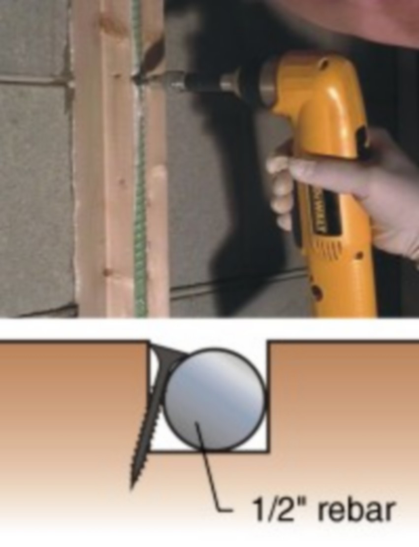
Catch the rebar under the head of the screw. The rebar will be just below the surface of the 4×4.