Beam Me Up
Spring 2001

GET STARTED
FREE PRINT & DIGITAL EDITIONS
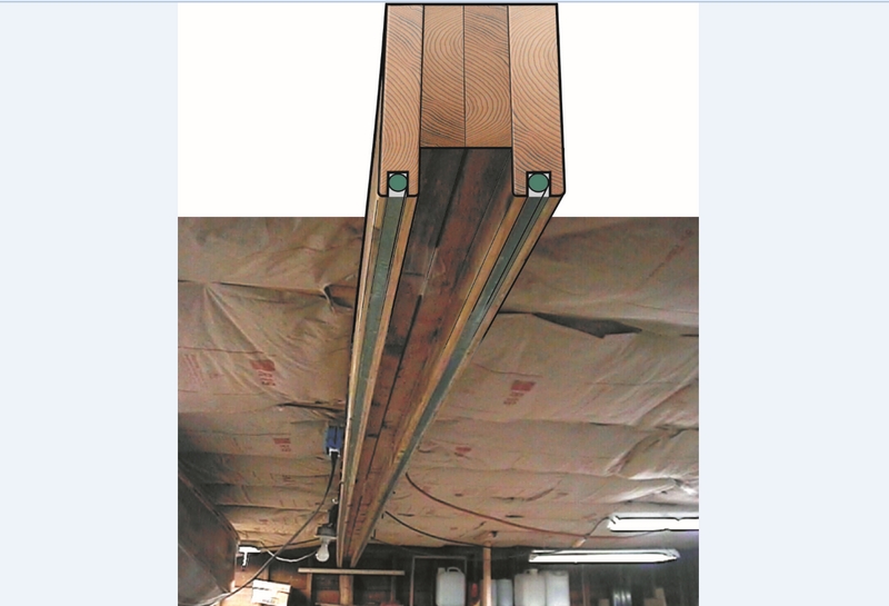
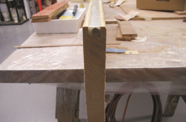
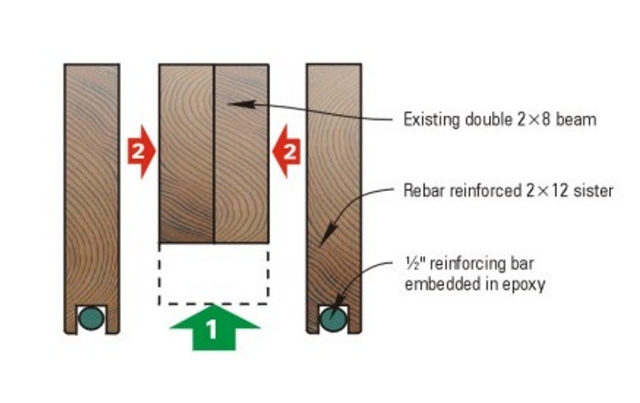
Above: The sister beams reinforce the failing ceiling beam to easily carry the load, with capacity to scare. Rebar is embedded into the bottom surface of the sister beams where the tensile load is at its maximum. (Figure 6)
While working in my shop/converted (never to be seen by a car) garage, I noticed that the double 2×8 beam supporting my ceiling joists was sagging about 2 to 3 inches in the middle. The builder of this forty-year-old garage didn’t use full-length 2×8’s to span the 19′ width, but four 2 x 8’s nailed together with staggered butt joints. Over the years, gravity took its toll. The nail holes elongated, the butt joints opened up, and the beam sagged ominously.
My plan was to jack the sagging beam to its original position and add sister beams—reinforced 2×12 to each side. I would install steel concrete reinforcing bar (rebar) into the two new 2x12s with epoxy using a technique similar to that in our Other Uses manual (page 11). After raising the existing beam to its original position, I would glue and screw the 2×12’s beams to each side to keep it in place. Here’s how I did it.
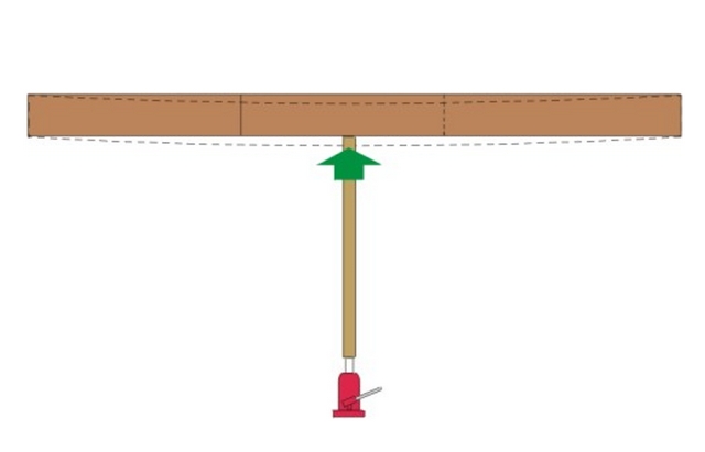
I screwed two 2×4’s together to make a post and braced it between the hydraulic floor jack and the center of the beam, making sure the post did not stick out past the sides of the beam (Figure 1). I slowly raised the beam back into place with long intervals to allow the house to adjust to the movement of the beams.
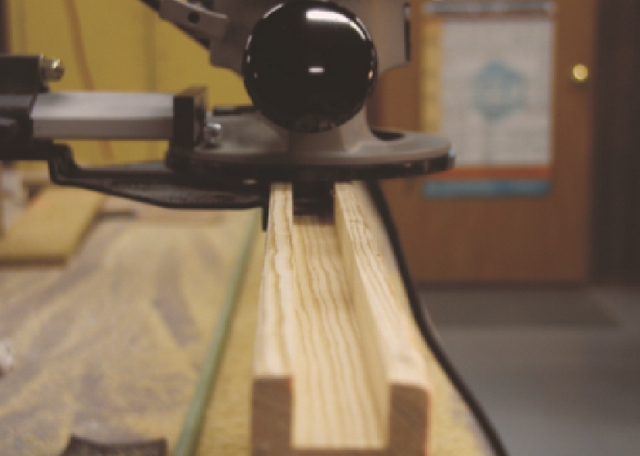
I purchased two, twenty-foot 2×12’s and two ½” diameter by 20′-long rebar at the local lumberyard. I set the 2×12’s on edge on sawhorses and used a router to carve a 3/4″ wide by ¾ ” deep groove down the middle of the bottom edge of the 2×12 sister beams. (Figure 2). A few passes of the router were necessary so that the router bit wouldn’t chatter. The rebar was positioned on the bottom (tension) side of the beam. After completing the groove, I sanded the inside surfaces to ensure there were no burnishes that would inhibit epoxy penetration.
Since the rebar was fairly clean, it required little preparation; a few areas had to be scuffed up with a wire brush. If the bars were oily or heavily rusted, they would need to be cleaned of rust, scale, oil, and dirt. Rebar is textured to key into concrete, or in this case, epoxy. Brian Knight used epoxy-coated rebar for a similar project that cost about the same as my uncoated steel. The epoxy-coated rebar may not require such preparation.
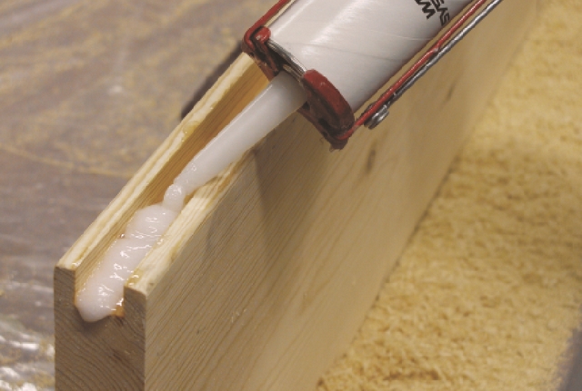
I mixed a small batch of neat (unthickened) WEST SYSTEM® 105 Resin®/206 Slow Hardener® epoxy and wet out the inside of the groove. Then I thickened the epoxy with 404 High-density filler to a mayonnaise consistency, loaded an 810 Fillable Caulking Tube, and filled the entire length of the groove half full of epoxy (Figure 3). Gravity was working for me and the epoxy wouldn’t drip out of the groove as it would have if the beam were in place and inverted overhead. When the rebar was inserted into the groove, thickened epoxy oozed out on both sides. I then used a spreader and filled the remainder of the groove with the excess epoxy (Figure 4). In areas where the rebar didn’t sit nicely into the groove, I used drywall screws on either side of the bar to sink it fully into the groove. Because my unheated shop was cool, I allowed the epoxy to cure for a few days to assure a thorough cure before moving the beams.
While the new sister beams were curing, I prepared both sides of the existing beam, using an orbital sander with 60-grit sandpaper. This removed any dust and dirt (and cobwebs) that had accumulated over the years and created a nice rough surface for the epoxy to adhere to. I then screwed a cleat onto the wall below each end of the drooping beam so that I could support my new beams close to the existing beam. I could then dry-fit my new beams by rotating them into position to make sure they would fit in the space. This also allowed me to practice the assembly process so it would go smoothly and quickly.
Once the beams fit properly, I mixed 105/206 thickened with 403 Microfibers to a mayonnaise consistency. Since the new beams were lying on their sides ready to be rotated into position, it was easy to apply thickened epoxy to the horizontal surface. My wife Jill (right-hand-woman and project expediter) mixed the epoxy as I applied it. When I was almost finished with one batch, she would start a new one so that the whole project continued without downtime.
Once both surfaces were coated, I rotated the beam into position and screwed to the original beam with drywall screws (Figure 5). In areas of the beam interface that needed more encouragement than the screws alone could provide, I used large C-clamps to force the beam faces together.
The jacks stayed in place for a few days to allow the epoxy to cure thoroughly in the low temperatures. In warmer conditions, the jacks could have been removed in a day or so. Once the stress was relieved from the jacks, the newly reinforced beams easily carried the load and there was minimal deflection (Figure 6 at top). The ceiling was back in service and I didn’t have to worry about the sky falling in my shop.
This technique has also been used in boatbuilding to build strongbacks that support temporary frames and to reinforce molds.


