

by John R. Marples
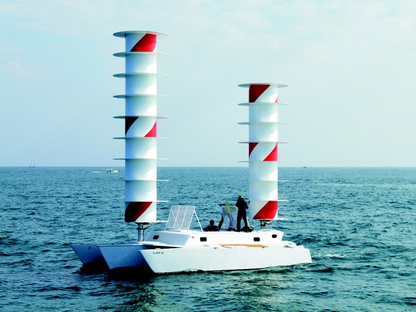
Above: Project Brighter World on demonstration day. The boat performed very well, sailing at windspeed even though it was about 30% heavier (due to the heavy batteries) than the normal sailing vessel design weight. The project was considered a tremendous success.
In early 2007 Impossible Pictures of London, U.K. approached me to participate in a boat demonstration using a Flettner rotor-powered trimaran. They were filming a demonstration for the Discovery Channel’s Project Earth series. Our program would be called Brighter World. Two atmospheric scientists, John Latham and Stephen Salter, had devised the Albedo effect, a way of changing the reflectivity of clouds to deflect some of the sun’s heat, cooling the oceans. It required a flotilla of vessels to seed clouds with small saltwater particles. Our trimaran would be a prototype for this type of vessel.
The scheme called for installing a couple of specially built rotors on a boat. We purchased a used Searunner 34 power trimaran (a boat I co-designed with Jim Brown in the 1970s) in Florida and trucked to our building site in Fort Pierce, on Florida’s eastern coast. We chose the location for its access to tropical-colored water.
We built two 4.5′ diameter rotors. The forward (main) one was 27′ long and the aft (mizzen) was 21′ long. They were sized and positioned to center the lift in a similar place to the sail-powered version of the Searunner 34. A 48 DC electric motor (golf cart motor) powered each rotor from a bank of batteries wired through a speed controller. The controller throttle access was conveniently positioned in the cockpit for the helmsmen. Battery charging required a shore power plug-in at the dock.
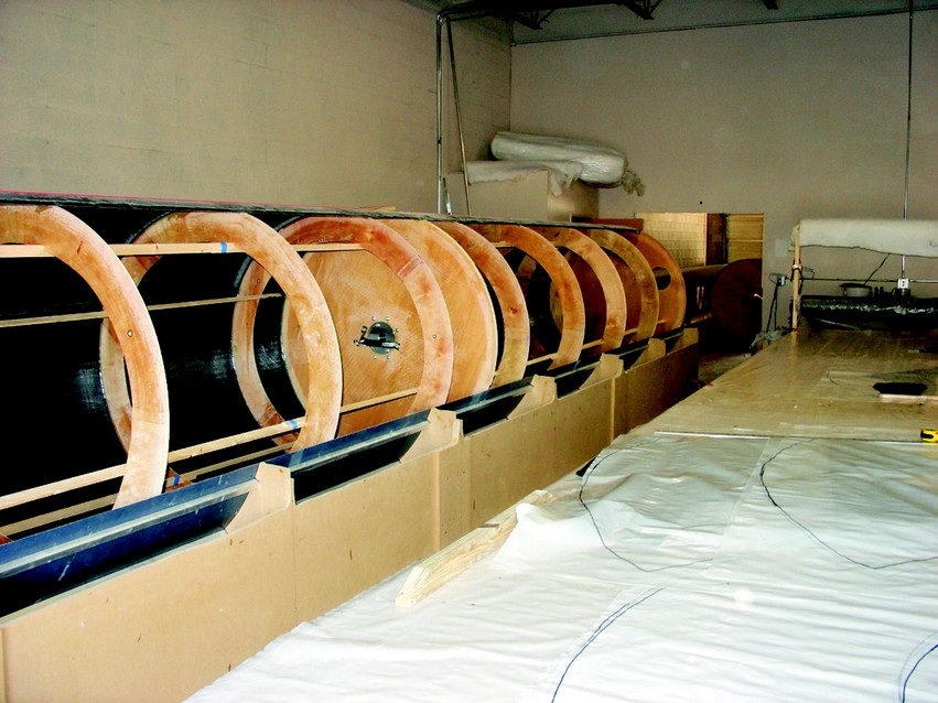
Each rotor was a large, smooth cylinder, supported by ball and roller bearings. In addition, fences—8′ diameter discs—were added to the cylinder about 3′ apart to improve lift performance. Since the surface area of the fences and cylinder was quite large, we chose a foam/carbon fiber sandwich construction to keep the weight down. We made each cylinder in a cylinder mold in four longitudinal sections with joggle seams at the joints. Coring foam was beveled at the edges and omitted at the joints and bulkhead attachment areas. The 27′-long panels weighed about 25 lbs and the 21′-long panel about 19 lbs.
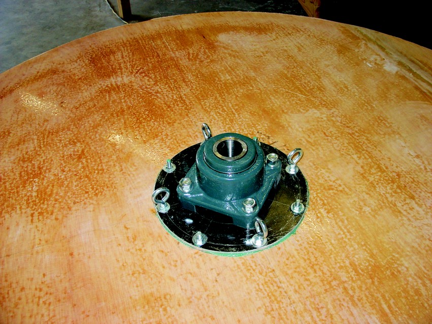
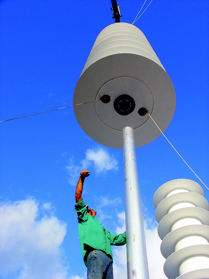
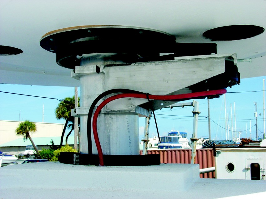
The rotors were supported on the boat by aluminum tube stub masts that went halfway up the rotor to the mid bulkhead. A pin on the mast top supported a roller bearing, carrying the full weight of the rotor. Another larger ball bearing at the bottom maintained the rotor alignment on the mast and provided an attachment point for the cog belt drive system. We added major structural reinforcement to the boat deck, cabin top and flooring to support the weight and bending moment of the rotors. It was crudely done using multiple layers of plywood to resist the side loads created by the rotor lift.
They Cylinder Mold
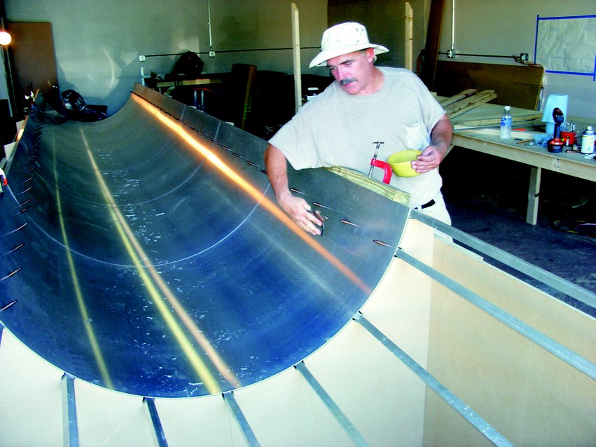
Panel construction employed a metal surface, partial cylinder mold, and vacuum bag layup. Cylindrical accuracy for the finished rotor was crucial since it was intended to operate at 400 RPM. (That equates to a surface speed of about 65 miles per hour.) Minor weight differences between panels could cause significant imbalances in the finished rotating structure, so we need the lay-up consistency to be as accurate as possible. The sheet metal pieces were butted together on each mold former. Project Brighter World A Flettner rotor is designed to use something called the Magnus effect for propulsion. The Magnus effect is a force acting on a spinning body in a moving airstream that acts perpendicular to the direction of the airstream. It gives the pitched baseball its curve, the golf ball its slice.
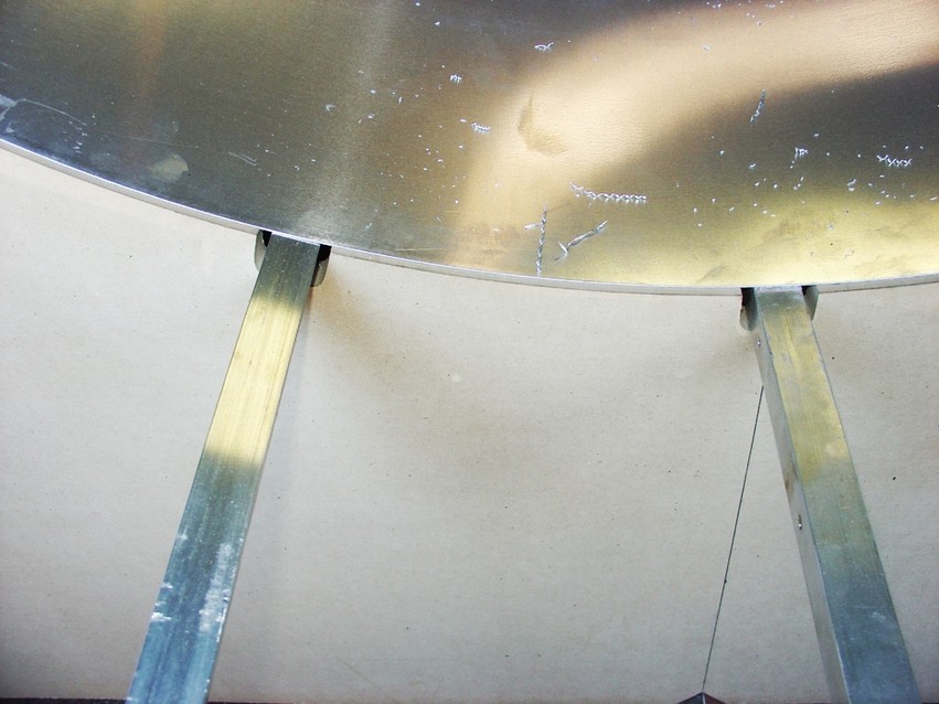
We chose MDF sheets and aluminum for the mold structure and surface to assure the accuracy of the component parts. Using cutting fixtures, we made the MDF formers identical. The radius was rough cut and then trimmed with a router on a pivot arm. We assembled the sidewalls full length, keeping the lower edge perfectly straight. All formers were screw-fastened to the sidewalls on 4′ centers and registered with the lower edge. The upper corners of the radius cutout were sighted to check the optical alignment of the formers. Then the aluminum square tube stringers were screw fastened into notches in the formers and adjusted to make sure the inside surface touched the radius. Small wood wedges were driven under the sidewall for adjustments to level the mold assembly. We tried to verify the alignment with a laser level, but it was not sufficiently accurate for our needs. Once the mold was adjusted, but before we installed the sheet metal surface, it was glued to the floor.
The mold surface was .040 aluminum sheets, 4′ wide by 6′ long. Each sheet was butted to its neighbor, with the butts centered on a mold former. The sheets were merely pressed against the formers and stringers, and pop-riveted to the top two stringers. Self-adhesive aluminum foil tape was used to cover the butt joints on the molding surface, rendering them air-tight. The foil tape was very thin and when burnished, was less than the thickness of a coat of paint. Sunlight reflections on the mold surface indicated it was very smooth and fair.
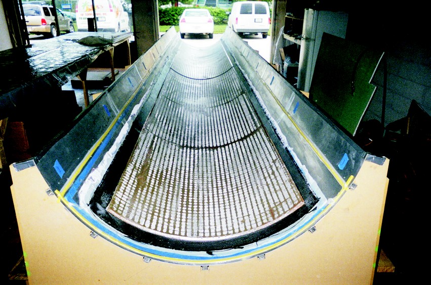
To prepare the mold for the operation we mapped out the panel size on the mold surface and also marked off the vacuum seal locations. We also glued a strip of .040 aluminum sheet about 2″ wide to the mold to create the joggle on one edge of the panel. Then we gave the molding surface five coats of mold release, hand rubbing each coat to ensure a non-stick surface.
Project Brighter World panel layup
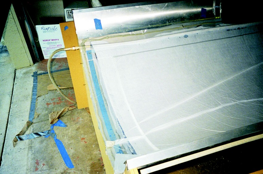
The panel construction consisted of 6 oz plain weave carbon fiber cloth on each side of ½”-thick H-80 Divinycel contour core foam. We started the layup with nylon release fabric against the mold, then used squeegees and a roller to wet out carbon fiber cloth. The foam core was precut to dimension and coated with a light mixture of epoxy and 407 Low-Density Filler to fill the surface voids. We transferred the wet foam onto the carbon cloth and positioned it. That was followed by release fabric, baby blanket.
The panel was built of ½”-thick Divinycel foam between layers of 6 oz carbon fiber cloth laminated with (quilt batting) and finally, the bag (4- il poly film). The vacuum manifold was already in place and covered with masking tape. We pulled the tape off the manifold and the vacuum seal and attached the bag, with the pump running. Soon the bag was compressing all layers and the vacuum gauge normally showed about 23″ of vacuum.
The rotor assembly
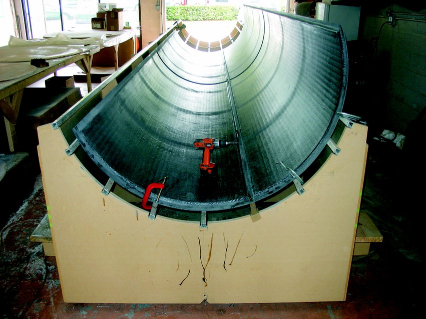
Each Project Brighter World rotor was made from four panels longitudinally fastened with epoxy. To prep the individual panels we scuffed the bonding surfaces and trim the panels to exact size. We removed the sheet metal mold surface and fastened the panels for the first joint to one of the aluminum square tube stringers with Cleco fasteners. The mold formers and perfectly straight stringer accurately kept the cylinder shape while the epoxy cured. Next, the three ½” plywood bulkheads were positioned and epoxied in place, followed by a third panel. Next, we added more ring frames and mechanical gear, then glued the last panel in place. All the longitudinal joints used Cleco fasteners to position and clamp the panels together during epoxy cure. They worked very well as long as they were oiled before use to prevent epoxy from clogging the moving parts.
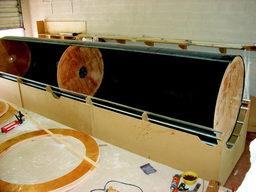
Experimental work published by Thom in the 1930s showed a significant increase in lift created by the rotor if large discs were added. We duplicated his work on our rotors with 8′ diameter discs added on 3′ centers. Each disc had the same layup schedule as the rotors and was made on a special round table. A router on a pivot arm was used to trim the fences and maintain dimensional accuracy. With the rotors supported on a rotation fixture in the shop, the fences were positioned, wedged in place and adjusted to run true by slowly rotating the rotor. Once adjusted, they were glued in place with large epoxy fillets on both sides. We painted the assembly while it was still on the fixture.
Installation
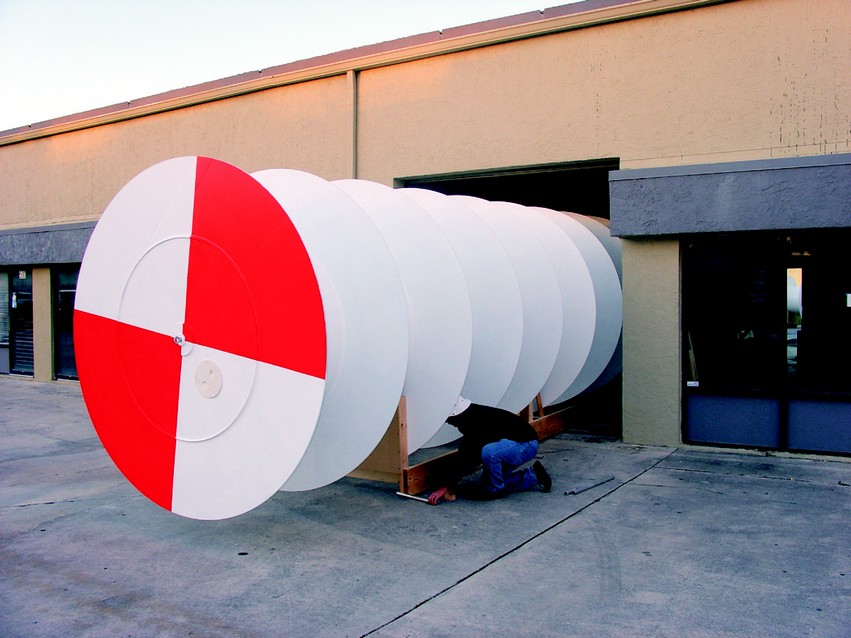
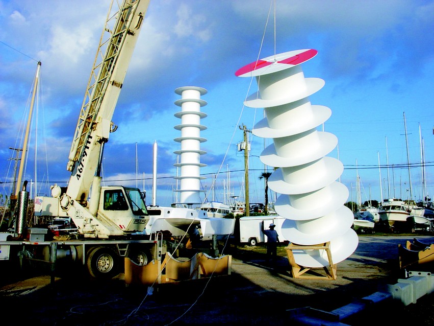
A crane lifted the rotors into position and slowly lowered them onto the mast. We did this early in the morning before the wind came up. The rotors had to be threaded onto the mast perfectly vertically so that the bearing pin at the masthead would engage the bearing bore on the middle bulkhead, which was only 1½” in diameter. The bearing pin had a machined “dunce cap” nut to help hit the target bore. It all worked very smoothly, thanks to the expertise of the crane operator. All three bulkheads were installed and a third panel was added. Ring frames and other mechanical gear were installed before the fourth panel was added. The rotor is lifted by the eye-bolt in the top bulkhead. Note the “tilt-up fixture” to prevent damage to the fences. Rotor roll-out. Pipe rollers make it easy to move the rotor into position for transport. It was then lifted onto a trailer by a crane.
Each rotor was powered by a 10 hp, 48-volt electric motor with a speed controller and a bank of 6-volt batteries. The motors were mounted to the mast on clamp brackets of welded aluminum. A cog belt using pulleys to achieve the correct speed ratio spun the rotors at 400 rpm maximum. The system worked very well without any adjustment from the first run. The initial design called for the boat to be carpeted with photo-voltaic panels to charge the batteries, but we did not have the money or the time to install them.
The Drive System
Project Brighter World demonstration day
We towed the boat about a mile offshore in light winds for the demonstration. At first, the boat bounced around in the light chop and swells, but as soon as the rotors started turning, the boat stabilized and became very smooth. We achieved 6 knots boat speed in 6 knots of wind at the best run of the day. Kevin, the “presenter” put aboard for the filming, was initially rather skeptical about the boat’s potential. But by the day’s end, he ran out of superlatives to describe the performance. The whole crew was pleased with the show. The demonstration sailed with about 8 hours of powering time for a single charge on the batteries. Since the winds were light and the rotors only rotated to less than 200 rpm, we had over 12 hours of running time. The rotors were lowered carefully over the stub masts. The mizzen rotor is being installed. The main rotor is already in place. The 10-hp drive motor is clamped to a bracket on the mast. A cog belt drive system connects the motor to the rotor. It worked flawlessly. Demonstration day. The boat performed very well, sailing at wind speed, even though it was about 30% heavier (due to the heavy batteries) than the normal sailing vessel design weight. The project was considered a tremendous success.


