New Beach Cat (Part I)
Spring 1995

GET STARTED
FREE PRINT & DIGITAL EDITIONS
Spring 1995
By Captain James R. Watson
In issue Epoxyworks issue #4 I wrote about the construction of new hulls for my Hobie-14 catamaran and discussed details that made building it easier. Well, as with most building projects, it was not completed on time. I can blame only this summer’s excellent sailing conditions for the delay. Whenever I had time to work on the boat, I went sailing instead. Of course, my reliable Hobie-14 sitting on the beach was the source of my summer-long delay. Heck, I support the concept of “take your time and enjoy the building project rather than rush through it.”
The delay proved beneficial because it allowed a new opportunity to come along and also allowed me to further study my intentions for the ultimate beach boat. The original concept was to simply replace the Hobie-14 hulls, retaining all other components. But an old sailing friend showed up one day and offered me his wrecked Hobie 17. It had all of the components except the hulls. I got a mast, sail, beams, rudders, centerboards and so on. What luck! Suddenly, I had a craft with 168 square feet of sail rather than 118, and I was able to keep my current Hobie 14 intact, rather than cannibalize it.
The Hobie-17 option permits a higher performance version. If the Hobie-17 rig is too much power for me, I’ll put on one reef equivalent to a Hobie-14 sail. What you really intend to do with the craft is the most important detail in finding the design that suits you best.
Even with a small craft such as this, there are all sorts of systems that you must deal with in detail to contribute to satisfactory sailing performance. Since I had already worked out most of these details and completed much of work on the hulls, they had to be modified for the Hobie-17’s components and loads.
No matter whether a Hobie-14 or 17, the beams must be attached securely to the hulls. For the Hobie-14 conversion, I had fabricated mahogany pylons that slipped over reinforced bulkheads. The cast aluminum connectors of the trampoline/crossbeam assembly would simply slip over these the same way they would over the stock aluminum extrusions. A plywood template helped in shaping the pylons to match the opening in the aluminum connectors.
For beams that mate directly to the hull, as with the Hobie-17 configuration, a totally different arrangement was needed. The pylons I had spent so much time on were history–fortunately they weren’t bonded in yet.
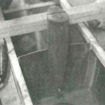
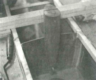
The two main bulkheads in each hull were positioned to match the Hobie-14 trampoline dimensions. Since the beams are farther apart on the Hobie-17 than they are on the Hobie-14, I had to install a new bulkhead at the new rear beam locations. The front beam and bulkheads stayed where they were. I fashioned laminated mahogany blocking and bonded it to the inner skin of the hull on each side of the bulkhead. The blocking butts to the underside of the shear clamp and is designed to transfer the loads from the beam attachment hardware into the hulls .
The curved beams will now sit in a raised saddle (of mahogany) on the inner edge of the hull and a recessed pocket at the outer edge of the hull. The end of the beams were used as a mold to build the pocket. After first covering the beam ends with 6-mil plastic sheeting, I laminated five layers of 6 oz. fiberglass fabric over the beam. (Five layers of 6 oz. fabric yields about a 1/16″ thick laminate). I trimmed the cured fiberglass laminate to shape and positioned it in a cutout in the short section of deck I installed. A notch was cut in top of the bulkhead to hold the fiberglass pocket at the correct angle and depth.
After covering the aluminum beam ends with plastic, I positioned the ends in a bed of thick epoxy spread in the wooden saddle and the fiberglass pocket. With the hulls properly aligned, this arrangement fixes the beams’ location and position in cast epoxy on the hulls. But, the beams must be firmly joined to the hull to resist racking and torsional loads the hulls may impose in sailing conditions. The bolts that hold the catamaran’s cross beams in place will be subjected to heavy tensile loads. They must be very reliable. Complicating matters, I wanted the beams (and the bolts) removable.
With the beams in position, I drilled 5/16″ diameter lead hole through the aluminum beams and into the laminated block reinforcements. I placed tape on the drill bit to establish the desired 3″ depth into the blocking. Next, I removed the beam and increased the hole diameter in the blocking to 3/8″, then ½” then reamed it to 9/16″ with a wood spade bit. Enlarging the lead hole in small increments insures that the original path of the lead hole is maintained. The final 9/16″ diameter permits the nuts for a 5/16″ bolt to just fit in the hole while the points of the hex head prevent the nut from spinning in the hole. It’s just tight enough to temporarily hold the nut in place with the bolt removed. (I used 5/16″ threaded rod as a temporary substitute for bolts.)
After drilling I found the bolt would no longer go to the bottom of the hole. I shined a flash light into the hole and discovered it was half-filled with saw dust. I inserted ¼” copper tube into a short piece of rubber hose and pushed the hose into the small end of a funnel. I placed the end of my shop-vac into the funnel and sucked the holes clean.
I turned four nuts onto each of the bolts, spacing so one was near the end, one flush with the top of the hole and two spaced evenly between them. To prevent the bolts from becoming permanently bonded in place, I sprayed the threads with non-stick cooking spray. Now I was ready for the bonding procedure. I poured resin and hardener mixture into the clean holes and let it set for five minutes. The epoxy readily penetrated the endgrain in the holes and I topped them off as the epoxy level dropped.
After coating the threads with thickened epoxy, I slid them into the holes and wiped the excess epoxy that squeezed up as the bolts and nuts were installed. After all the bolts were correctly positioned I let the epoxy cure.
The next day, I removed the rods, replaced the cross beams and tightened them down securely to check their position. We have conducted extensive tensile testing of 5/16″ inch bolts bonded this way, and have found it is safe to rely on a working load of about 1,000 pounds per inch of buried depth until the bolt’s tensile strength is reached.
When my friend offered me the Hobie-17, the chainplate configuration changed. Now I had to attach it to the thin plywood hull. The high load from the rig had to be dumped into this attachment point, in a way that would effectively distribute the forces into the hull. This was accomplished by bonding a laminated block of mahogany to the plywood hull, with the top of the block butted to the underside of shear clamp (similar to the beam bolt reinforcing, but without the bulkhead). The block’s grain is oriented vertically, in the direction of the load path. (Plywood is a poor choice for the block, as half the wood grain runs in the wrong direction.) I beveled the the block at the sides and bottom to reduce stress concentrations and save weight. The bottom end of the block butts into the sub-level. I covered the block with 3mm plywood that laps onto the shear clamp. For the hardware attachment, I took the ends of a turnbuckle and bonded them into slightly oversized holes drilled through the shear clamp into mahogany block. Tensile tests (one-time loads as well as fatigue) indicate this arrangement will be highly reliable.
Similar attachment points are intended for the forestay bridle and the anchor/mooring bridle. The mooring bridle is a U-bolt, buried deep so it is nearly flush with the stem contour. Its legs are bonded into a wedge-shaped block, which is bonded into the narrow cleavage of the bow. I carved some of the stem away, and rounded it for fastening the painter. It is mounted low for optimum towing and mooring performance. I bonded several layers of 9 oz. fiberglass to each side of the eye to provide reinforcement in the event of high side loads.
A trapeze is fun for day sailing, and also effective at increasing righting moment. Footholds along the gunwale are essential when on the trapeze. Such a hoop also works well as a handle for moving the boat on the beach. When things get really wild, I like having a handle just to hold onto, (one hand for the ship, and one to hang on). I use 1/8″ diameter rope fashioned into a hoop, and bond each end into a gunwale reinforcement block.
To bond the rope in, I drilled holes 2½” deep and the same diameter as the rope. With a piece of line 13½” long, I place masking tape about the 2½” from the ends. It’s not a bad idea to slip a 7″-long piece of ½” flexible tubing or garden hose over the line and bond it in place as you would a bolt. I always dip the line in epoxy up to the tape, and thoroughly wet the hole with epoxy, carefully wiping excess away as the rope displaces the epoxy in the hole.
The hulls of my catamaran should never leak. But moisture still finds its way inside through condensation, or because I’ve inadvertently left off the access plate in the rain. At temperatures of about 90°F, even a tiny amount of water can turn inside of a boat into a steam box.
The screw-type access hatches have a tiny hole drilled in them to prevent pressurization of the hull. This simple countermeasure can also provide active drying of the enclosed hull. The hole “exhales” moist air when the air inside is warmer than the ambient temperature, and “inhales” dry air when the air inside is cooler.
Another step I’ve taken to promote drying, is to cut 2½” diameter ventilation holes in all bulkheads. Looking at the arrangement, you might think it was designed to save weight. These openings are often referred to as “lightening holes,” but the pile of 3mm thick plywood discs I cut out actually weighed next to nothing. However, the cutouts do permit air to pass through the long, tube like hulls, assisting in drying them.
It was especially important to coat the exposed endgrain of the cutouts. I applied three coats of WEST SYSTEM 105 Resin® and 207 Special Clear Hardener to protect the wood from moisture. I built a similar boat in 1970 and it’s still sailing. It has no rot and weighs the same as it did when new, testifying to the effectiveness of this approach.
On several of my boats, I’ve installed silica gel bags to facilitate drying. I made these by pouring silica gel (a desiccant, available from florists) into a nylon stocking. Periodically, I warm the bags in an oven to dry out the crystals.
Although I have a small boat, I often sail quite far offshore. (Only experience sailors should undertake such ventures, and only in predictable conditions. Safety is the rule.) This is a fast boat, and there is always the possibility of hitting debris. This could result in serious damage to the boat’s thin 3mm plywood hulls.
My dad built a little scow many years ago, and in his wisdom filled the sealed hull with empty bleach jugs. They were great insurance against sinking, weighed next to nothing and were absolutely free. (He was sort of doing his part in recycling, too.) A one gallon jug will support about 8¼ pounds. Just before I close up these hulls, I’ll drop about 20 such jugs in each for plenty of emergency buoyancy.
The only problem my dad had was that when his little scow heeled or tacked, the darn jugs would roll around inside the hull and make a lot of racket. To prevent this, I’ll place a strip of 883 Sealant on the jugs’ contact points. This will help keep the jugs in position, but not so rigidly as to cause stress concentrations.
When the boat is resting out of the water, bunks that match the hull shape help distribute loads. This craft rests in bunks that fit it exactly. I made them by inverting the hulls and placing a 12″ wide piece plastic sheeting over the hull at the two main bulkheads. I then placed a 6″ wide piece of ¼” thick, firm, closed-cell polyethylene foam at these locations and taped them to conform to the hull shape. Next, I wet out three layers of 727 Biaxial tape and laid them onto the foam. I covered this wet laminate with release fabric and smoothed them out. When the epoxy cured, I removed the new laminate from the hull, trimmed them and bonded them to scrap ¾” panels with a cut-out in the general profile of the hull. Thickened epoxy bridged the gap between the laminate and the rough cut-out.
For more on the building of Captain Watson’s beach cat, Read New Beach Cat (Part 2) — Final Details.