By Greg Bull — GBI Technical Advisor
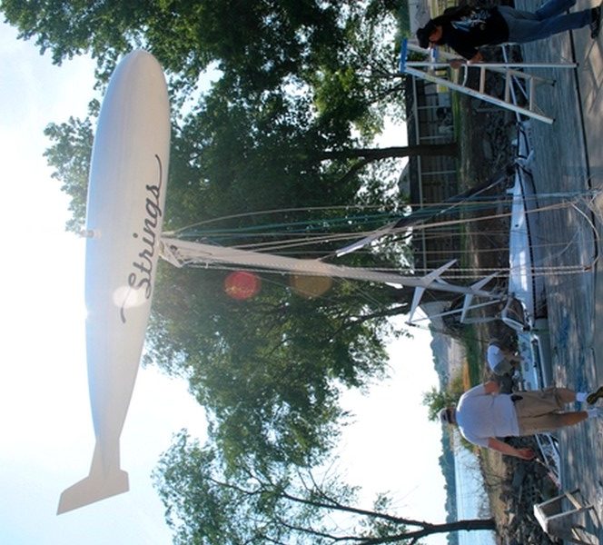
When Jan Gougeon built Strings in 2010 one of the most interesting features he included, at least from my point of view, was the masthead float. Due to its zeppelin-like shape, this is also called a blimp or a dirigible. The purpose of the float is to make the boat self-rescuing: if the boat tips, the float prevents it from going any farther than lying on its side. The mast and float are then used to right the boat. Jan developed this system when designing the Gougeon-32 back in the late ’80s, so he thought it would work for Strings.
Jan built the float by making a half mold to build the two halves from, then gluing the sections together. He simply used pink insulating foam board (Owens-Corning Foamular® InsulPink®) 2″ thick that he picked up at our local home improvement store. To create the desired thickness he glued the pieces of foam together with WEST SYSTEM 105 Resin/206 Slow Hardener with 410 Microlight filler mixed to a catsup consistency.
He roughed out the shape with a rasp followed by a coarse file and 36-grit sandpaper on a wooden sanding block. When it reached the shape Jan was looking for, he added a thin coat of thickened epoxy over the entire surface and let it cure. He smoothed this down first with 36-grit sandpaper on a sanding block, then moved up to 80-grit and finally 220-grit. This completed the mold.
He waxed the mold surface then laid a layer of carbon fiber fabric over the mold with 105/205 and allowed it to cure until tacky. Next, the surface was coated with epoxy filled with 410 Microlight. The next day the sanding started again—this time to smooth the outside of the dirigible. It was easier to sand the outside with the part still stuck to the male mold surface and get it really close to the final smoothness.
When the fairing was done, Jan made a stuffing jig. The stuffing jig served a couple of purposes: 1. To hold the half-round part so work could be done on the inside and 2. to create a flat plane to trim the half dirigible to. The stuffing jig would also help in the final assembly.
When the jig was completed, the first half of the dirigible was pulled from the mold and put into the stuffing jig. It had been left on the mold during the jig building process to maintain the correct shape. Jan laid up the second half the same as the first, again fairing the outside.
With the first half of the dirigible held in place in the jig, the structure could be installed on the inside. This is where Jan came up with the great idea of using just tows of carbon fiber to create a gridwork on the inside of the dirigible half, like small frames or ribs on 2″ centers. The tows were laid lengthwise first (the long way) then across (the short way). This added a lot of structural reinforcement with minimal weight.
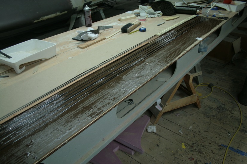
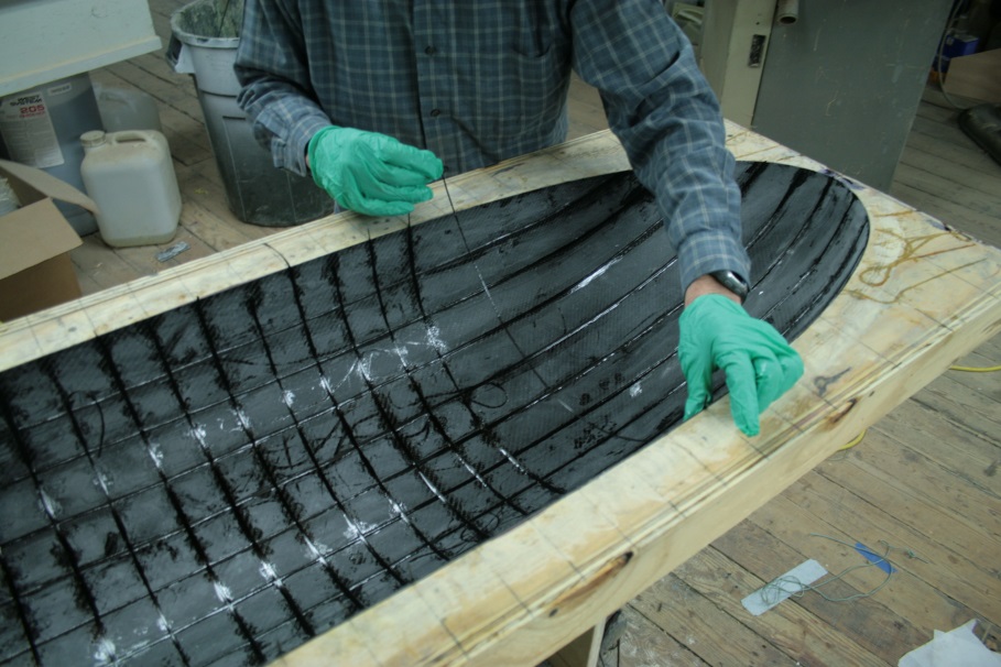
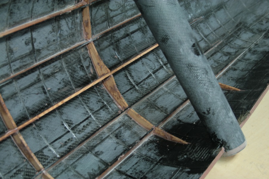
Where the pivot tube goes through to attach the dirigible to the mast, more reinforcement was added. Strips of 1/8″ x 1/2″ thick clear spruce function as stringers positioned on or next to the carbon tows bracing the area around the tube to help carry the load.
Putting an internal flange on the inside perimeter of the dirigible halves allowed the assembled dirigible to be smooth on the outside. The temporary backer for the flange was made of plywood covered with plastic, then screwed down to the jig with the plywood protruding into the inside of the dirigible half by about 1″.
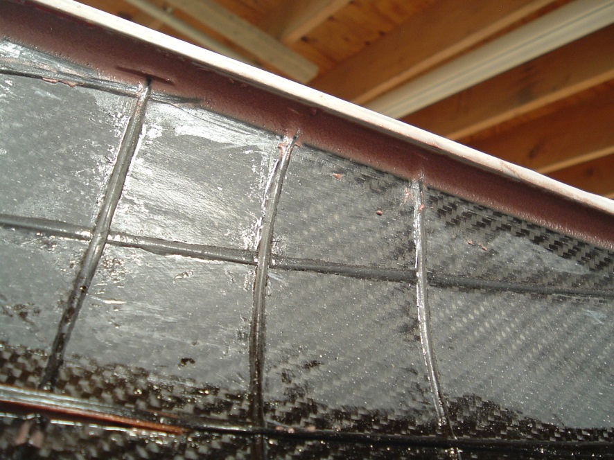
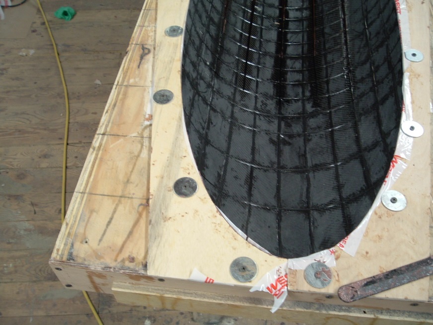
Jan applied 105/205 mixed with 407 Low-Density filler to a peanut butter consistency. He used the rounded end of mixing stick to fillet the corner formed by the plywood and the edge of the dirigible. After the fillet cured, the temporary plywood backer was removed. This made a smooth bonding area on both halves and provided a larger surface area for joining the two halves. Having more bonding surface area allowed him to apply a thinner coat of thickened epoxy to create minimal squeeze-out when he joined the two halves. The squeezed out thickened epoxy was smoothed over the surface of the seam. Carbon fiber tape, 2″ wide, was then applied along the seam, adding strength.
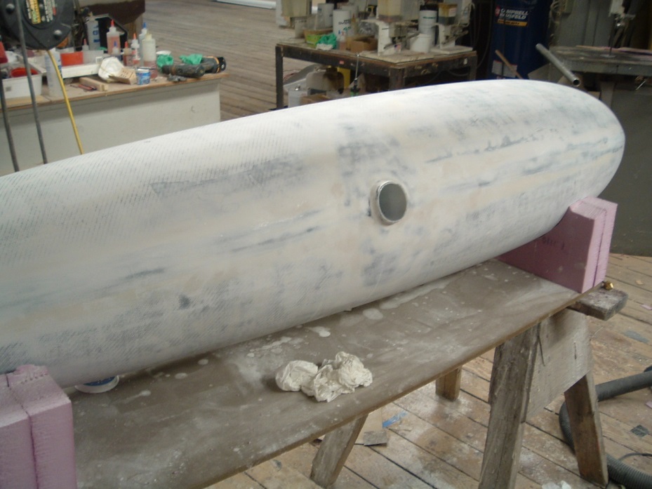
For fairing, 105/205 thickened with 410 Microlight was again spread across all surfaces. Most of this fairing compound was sanded off so that you could see black carbon through the fairing, but he didn’t sand into the carbon. This took a couple of applications to reach the desired smoothness. Once this was achieved, paint was applied to match the rest of Strings.

