Improved Mold Strongbacks
Spring 2006

GET STARTED
FREE PRINT & DIGITAL EDITIONS
Spring 2006
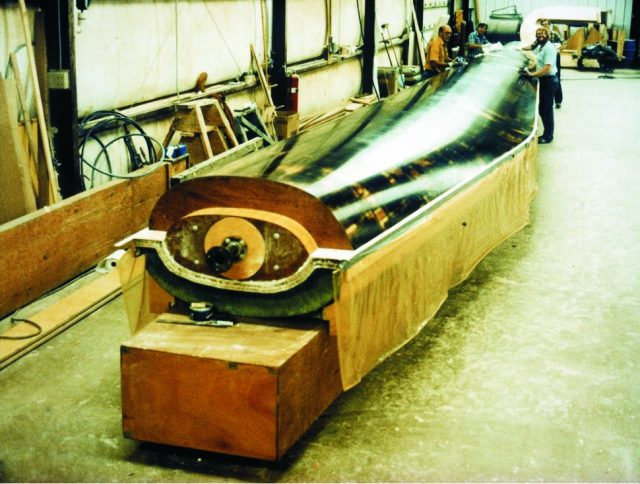
Above: Three 8″ plywood supports isolate the mold from the mold strongback.
Back in the 1980s, Gougeon Brothers, Inc. was one of the largest producers of wind turbine blades in the US. The blades were built of wood veneer and epoxy, and varied in length from 10′ to 70′. They were built in halves and vacuum laminated in female molds built with WEST SYSTEM® Brand Epoxy. Tolerances were tight, and every aspect of the tooling was critical, from molding to assembly. If something wasn’t right when the two halves were glued together, there wasn’t much you could do to make it right later.
The most difficult tolerances to maintain were span-wise straightness and twist. Early strongbacks for molds and assembly jigs were made of wood and were built like tall and skinny “I” beams. Initially, everything worked well. But as the seasons changed and the wood picked up moisture, and the summer temperatures in the shop went up, we were pushing the limits of the tolerances. The engineers figured it was a combination of forces caused by wood’s volumetric change, with changes in moisture content and difference in coefficient of thermal expansion between the wood strongback and epoxy/fiberglass molds.
Our short-term fix was to cut the mold free from the strongback and isolate it with plywood supports ( 3/8″ thick) that were installed perpendicular to the length and located every 16″ to 24″ apart. They ranged from 4″ tall at the root end to 12″ tall at the tip end of the mold. The differences in height were due to the fact that the molds were tapered to mimic the blade half-geometry (thick at the root end and tapered to thin at the tip). The plywood supports were attached to the top of the strongback and to the backside of the mold with thickened epoxy fillets. Separating the mold from the strongback with the thin plywood supports meant slight changes in length between the two did not cause a problem. This is because the supports easily deflected to allow relative movement but had almost no effect on span-wise straightness. Luckily the problem was caught early, but we decided we needed a better mold strongback design that would be more stable.
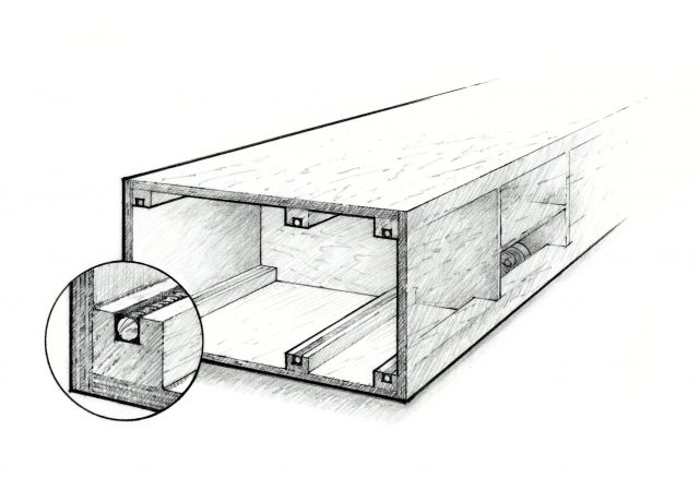
The solution was to make a box beam out of plywood and epoxy. This in itself provided significant improvement, but the engineers went one step further. They incorporated steel rebar originally designed for reinforcing concrete into the four corners of the box beam. The rebar, welded to full lengths, was glued into 2″×2″ wood stringers that ran full length along the four corners of the box beam. To make room for the rebar, a slot was cut into the wood stringers that was wide enough and deep enough to accept the steel. Epoxy thickened slightly with 403 Microfibers was used to fill the gaps in the groove surrounding the rebar after it was in position (Figure 1).
On molds up to 20′ in length, we used 3/8″ diameter rebar. On larger molds, we used ½” or 5/8″ diameter. The 70′ long mold strongbacks were reinforced with 6 stringers made of 5/8″ diameter rebar, one in each of the four corners and an extra one in the middle between the corners of the top and bottom.
When the strongbacks were used for blade assembly jigs or for saw jigs, they were anchored to the floor to keep things stable. If the strongbacks were used to support molds, wheels were mounted inside the strongback (on the larger molds) to keep the center of gravity low and to keep the height of the mold reasonable. On smaller molds where the width of the strongback was too narrow for a caster to pivot inside the bow beam, the wheels were mounted on the outside of the structure.
Mounting wheels under molds with strongbacks can present some dilemmas. The wheels tend to get in the way of your feet. If you mount wheels under the mold strongback, you need to shorten the height of the strongback to make up for the wheel height. Otherwise, the mold gets too high for people to work on. Unfortunately, shortening the height makes the strongback less stiff, which can be a problem.
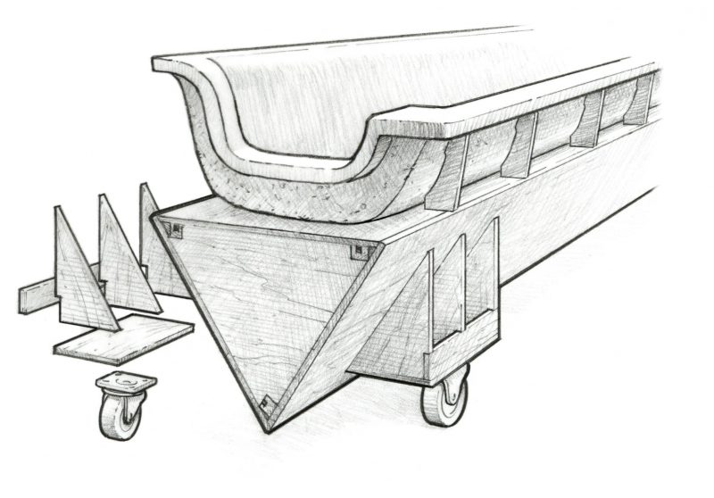
Mounting the wheels inside the strongback works best as long as you allow room for wheels to swivel without interference. Another option is triangular-shaped mold strongbacks. We found this to be the best solution for 20′ to 30′ mold lengths. By positioning one of the three sides horizontally, wheels could be mounted under the mold on angled brackets (Figure 2). This allowed room for the wheels to pivot without getting in the way.
After the blade halves cured, they were pulled from the molds, positioned in saw jigs, and trimmed along the leading and trailing edges. From there, the blade halves were moved to glue jigs where a shear web was installed on the inside of the high-pressure side. Eventually, the two halves were glued together with thickened epoxy.


