FREE PRINT & DIGITAL EDITIONS

SUBSCRIBE

6. Lay out the leading edge radius. The actual radius is a 90 degree segment of a circle drawn tanged to #0, bisected by the chord line. Its radius is 1.58% of the chord line length (c).

How to Loft Airfoil Sections

by Captain James R. Watson

When a designer chooses a foil section for a particular design, that section is often not produced to a close tolerance. I sailed on a boat that was noted for its erratic steering: the problem boiled down to an asymmetrical rudder. Optimization of the airfoil section translates into measurable performance and handling benefits.

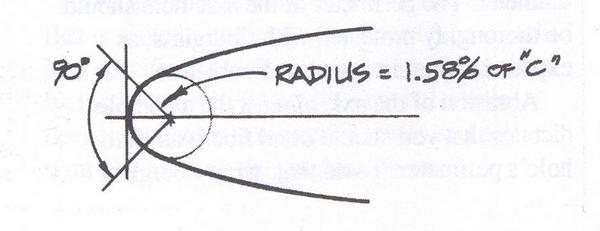
Whether you are going to build an airfoil from scratch or fair an existing foil with a template, you have to establish the section profile accurately.

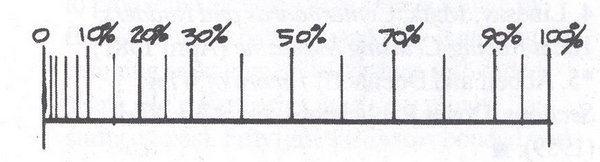
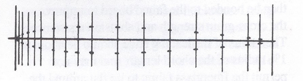
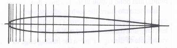
Airfoil sections of all NACA (National Advisory Committee for Aeronautics) families are obtained from dimensions off the centerline from specific station points. Station points begin at zero at the nose. The stations are spaced more closely in the forward third of the foil section’s chord length. This area carries more shape, thus requiring more reference points to define it.

Airfoils are cambered sections that are designed to produce life (with minimum drag) as they operate in a fluid (air or water). Certain sections produce the most lift with the least amount of drag for a given condition.

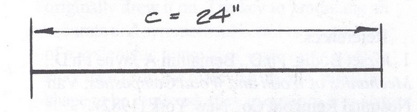
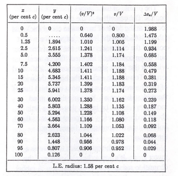
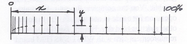
Chord line is defined as the straight line connecting the leading and trailing edges (or centerline). Station locations are expressed as a percentage, measured from the forward #0 station, of the chord line. Chord thickness is described as a percentage of chord line, measured in half breadths at a particular station.

1. Establish the airfoil's  overall chord line length (c); our example is 24".
1. Establish the airfoil’s overall chord line length (c); our example is 24″.
2. Refer to NACA 0012 Basic Thickness Form. Calculate a mark the station locations (x) which are a percentage of the overall chord line length, measured from 0%.
2. Refer to NACA 0012 Basic Thickness Form. Calculate and mark the station locations (x) which are a percentage of the overall chord line length, measured from 0%.
NACA Basic Thickness Form
3. Calculate and mark the y dimensions (thickness from the airfoil's chord line) at each station.
3. Calculate and mark the y dimensions (thickness from the airfoil’s chord line) at each station.
4. Duplicate the Y dimension points on the other half of the airfoil.
5. Connect the plotted points with a batten or ship's curve.
5. Connect the plotted points with a batten or ship’s curve.
6. Lay out the leading edge radius. The actual radius is a 90 degree segment of a circle drawn tanged to #0, bisected by the chord line. Its radius is 1.58% of the chord line length (c).
6. Lay out the leading edge radius. The actual radius is a 90-degree segment of a circle drawn tanged to #0, bisected by the chord line. Its radius is 1.58% of the chord line length (c).