Composites You Can Build
Spring 1994

GET STARTED
FREE PRINT & DIGITAL EDITIONS
Spring 1994
Composites have been on the automobile motor sports racing scene for some time now. Indy cars, Formula 1, IMSA GTP (International Motor Sports Association Grand Touring Prototype), and others employ composites to the fullest limit of the imagination (and budget). Engine builders are even beginning to use composites for internal components. Autoweek, Advanced Composites and similar magazines write about composites constantly. But most of these applications involve sophisticated techniques, tooling and materials such as autoclaves and resin-impregnated materials (pre-pregs). These require aerospace-level technology not commonly available or economical for the amateur builder. Pre-pregs and other advanced composites employ adhesives that require an oven to promote curing (post cure).
I’ve been racing stock cars for seven years now and I’ve found some applications where composites have solved problems and have offered some advantages. My composites are simple enough that I can make the parts in my shop.
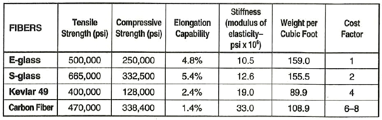
The reinforcing materials described in this article are listed in the table below with their relative physical properties.
Composite technology represents the cutting edge of today’s materials world. Composites are fast-evolving technology and the jargon of product names, materials, configurations and building techniques that you hear and read about. I’ll define these terms while describing three simple projects I built.
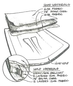
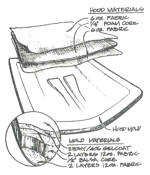
In the class I race, the rule book says that you can use fiberglass for the hood. The problem is, a stock hood measuring 5′ x 5′ weighs nearly fifty pounds. Fiberglass copies made of chopped strand mat weigh half that; around 25 pounds. Without hinges and ornaments these are for racing only. The version described here weighs 6 pounds and is much stiffer than a stock hood.
First, I needed a mold to build the hood. For this, I borrowed the hood of an IROC-Z from the local junk yard and applied five coats of mold release wax to it. Following this step, I applied the first surface coat of unthickened WEST SYSTEM® 105 Resin/206 Slow Hardener. Epoxy can fisheye over some mold release agents. When this happens, simply apply more epoxy. WEST SYSTEM 207 Special Clear Hardener resists fisheyeing and in retrospect would have been a better choice.
I allowed the first coat of epoxy to reach the gel state, which took about half an hour at 70° F. My second coat was epoxy thickened to a catsup consistency with 404 High-Density filler. I applied this mixture about 1/16″-thick.
Glass fibers won’t contour into tight corners, so in the crevices detailing the hood scoop, I applied a thicker build-up. When this mixture had gelled, I laid two layers of fiberglass fabric over everything, and wet out both layers, spreading the epoxy with a squeegee. Next, I placed 1/2″-thick end grain balsa onto the wet laminate and covered it with two more layers of fabric. (Instead of balsa core I could have used foam).
The core works like the web of an I-beam and the structural skins serve as flanges which bear the load. By separating the load-bearing skins you get a lot of stiffness with slight weight increase. Weight is not critical for the mold but it has to be stiff to retain the shape.
When the mold cured, it popped easily off the hood and was a rigid mirror image of the hood. The work didn’t damage the original hood and was returned, with a great wax job, to my junk yard buddy.
To produce a hood that would be strong yet light, I experimented. Using a variety of glass weights and cores I constructed 12″ x 12″ square panels. I weighed them and flexed them trying to imagine these as full size 5′ x 5′ panels.
I chose to use one layer of woven 6 oz. Episize™ glass fabric bonded to each side of ¼”-thick, closed cell, 5 lb. per cubic foot, crosslinked PVC foam core. I chose woven—rather than unidirectional—fabric because I anticipated multi-directional the loads on the hood. Woven fabric is easy to handle and stays put during bonding operations.
Grid-scored cores are common materials used extensively in boat construction. The core is scored into a ½” grid and held together by a polyester scrim. The grid score permits the core material to be contoured into and around compound shapes. When the core bends over a tight curve, the gap increases. The thicker the core, the greater the gap size. There is a vulnerable aspect to grid score (especially for below-the-waterline applications on boats) in that if the score is not filled, water can migrate along the channel-like gap and cause moisture damage. In addition, grid score may be visible through the laminate (a cosmetic flaw called print-through), especially as the gap increases. The problem with filling the grid score with adhesive is the extra labor involved and measurable weight increase.
To open the gap and allow me to fill in the grid score, I draped the foam over a 6″-diameter plastic pipe. I used epoxy thickened with 407 Low-Density filler to fill the grid score.
The test samples were flat panels made using the hand lay-up technique. The laminate is wetted and allowed to cure with no clamps or other pressure exerted on the laminate. However, the hood is curved, with details that are concave. The problem is ensuring contact between the skins and the core material in the laminate’s concave surfaces.
I once solved a similar problem by placing plastic over the laminate and pouring sand onto the plastic. The weight of the sand pressed the laminate together. But sand weighs only about 80 lb. per cubic foot so exerts only about .05 psi when poured 1″ thick. I would have to shovel a hundred pounds of sand onto the laminate, a lot of work for the relative low pressure it exerts. Worse, the mold would deform under this amount of weight.
There’s a better way. With vacuum bagging, air is evacuated from between an airtight bag and an airtight mold surface. The laminate is pressed together with force of 8–10 psi yielding a favorable fiber to resin ratio as well as pressing the laminate and core into all the contours of the mold. No weight is exerted on the mold.
I applied sealant to the perimeter of my mold. I coated the waxed mold with epoxy thickened slightly with 404 High-Density filler. About an hour later, I used a roller to wet the outer fabric skin with epoxy. I placed the skin into the mold, followed by the core material and then the top layer of glass. I covered the wet laminate with release fabric, then a breather material, then the bag film, attaching the edges to the sealant. I punctured the bag and placed a vacuum cup over the puncture. I don’t have a vacuum pump in my shop, but I do have an air compressor, so I used a venturi vacuum generator to evacuate the air between the bag and the mold. The breather blanket absorbed the excess epoxy. I maintained 8 psi of vacuum until the epoxy was cured. All of the vacuum bagging products I used are described in detail at WEST SYSTEM’s website on the Vacuum Bagging page.
Then I removed the bag, breather and release fabric, then removed the part. The finished surface was a perfect replica of the hood’s surface. I abraded the surface with an abrasive pad then spray painted it with PPG acrylic urethane paint. Despite high engine temperatures and a hot summer track, the hood has held up great. After more than 30 races, several crashes have fractured the skin and core, but these were easily repaired.
A gasoline engine produces more power when the fuel/air mixture temperature is cool. An air dam is designed to divert hot air from the carburetor and direct and accelerate cool air into the carburetor. I had experimented with air dam shapes made of metal and modified with plywood. I wanted to make a light, rigid composite part based on my highly evolved working model. First, I would build a mold from the model and then build a composite dam out of the mold.
I fabricated the mold over the working model that was screwed and pop-riveted together. I faired the transitions and modifications from my modified air dam with WEST SYSTEM 105/205 epoxy thickened with 410 Microlight.
When making molds it’s important to keep in mind that the quality of the surface finish will be duplicated, so extra sanding with fine grits pays off. As with the hood project, I applied a mold release wax to all of the surfaces.
For the flat areas and areas curved in one plane I used Formica® laminate. This is an ideal material because it already has a smooth finish. I use plastic tie wraps to hold together the Formica components that joined at angles (see Stitch & Glue Details for more information on using tie wraps.) For areas that lap, Cleco makes a great fastening clamp. Cleco fasteners will hold lapped parts firmly in contact until the epoxy cures.
I bonded woven fabric to the back side of the Formica and popped it off the original part. Final smoothing of the rounded area was done with 406 Colloidal Silica mixed with epoxy to a peanut butter consistency.
One of the material candidates for the air dam was Kevlar®, but it didn’t offer the stiffness I wanted, so I augmented with carbon fiber. I selected a hybrid material which offers qualities of both materials, resulting in a very lightweight, stiff structure.
Normal operating temperatures for race engines are around 200°F and the air dam must maintain structural integrity at these elevated temperatures, which are a hostile environment for epoxy. This is why I chose PRO-SET Laminating Epoxy to bond this laminate to shape. Its ability to remain structurally sound at elevated temperatures is the result of this epoxy’s high Tg or glass transition temperature. In addition, this epoxy wets fabric aggressively.
I wet-out the fabric on a plastic-covered table. I applied the epoxy with a roller, being careful not to disturb the light weave of the cloth. Then I carefully placed the wetted fabric over the mold.
As with the hood project, I used the vacuum bagging technique to consolidate the layers of hybrid fabric over this complex shape. I maintained the vacuum until the epoxy had cured, then removed the laminate from the mold.
The PRO-SET Laminating Epoxy’s physical properties are optimized with a post cure procedure. Post cure involves exposing the cured laminate to a specific amount of heat for a certain amount of time. This procedure will measurably improve the original cured physical properties. To achieve this I taped together a 1″-thick foam box slightly larger than the air dam and suspended a 200-watt light bulb inside the box. I stuck an oven thermometer through the wall of the box so I could monitor interior temperatures. If it got too hot I would simply turn the light bulb off for a while. I placed the air dam laminate in the unheated oven then turned on the light bulb. I controlled the oven so it warmed 10°F per hour until it reached 130°F, and held it at that temperature for 6 hours.
The finished air dam’s interior surface is glass smooth. The gold color of the Kevlar woven with jet black carbon fiber looks impressive. Even if I don’t go faster, it scares my racing competitors to pieces.
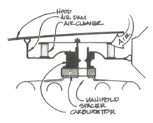
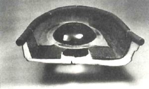
Class rules dictate a stock, iron intake manifold and a two-barrel Holly carburetor. A spacer is permitted to increase the plenum condition of the stock manifold. The spacer acts as an insulator keeping the carburetor cool as well as insuring a perfect seal between carburetor and intake manifold. Most of the racers use aluminum, but it conducts heat readily. Another option is laminated phenolic. It’s less conductive than aluminum, but is fairly difficult to machine. I wanted a carburetor spacer that was a better insulator, and something I could build and modify.
For dimensional stability I choose a sophisticated cellular material, wood. Specifically, non-laminated Honduras mahogany. I chose this species because of its excellent dimensional stability, relative hardness and bondability. I tested for conductivity by taping thermal couples to identical shaped parts then applied heat to the opposite side. I found that this material is half again better than phenolic and four times better than aluminum.
Using my drill press and router, I machined a spacer from a solid piece of 1″-thick mahogany. To get smooth, flat faces on each side of the spacer and assure a perfect seal, I first coated a small sheet of plate glass with mold release. After wetting out the glass with epoxy, I laid one layer of 6 oz. woven ceramic fabric on the glass and wet it out. Then I placed the machined mahogany spacer onto the wet fabric. I set a 4 lb. weight onto the spacer to ensure contact of the wood spacer, fabric and glass plate. When it cured I used a fine wedge of steel to pry the laminate from the glass surface. The result was a perfectly flat and very smooth surface. I repeated the procedure for the opposite side of the spacer, and trimmed the edges of epoxy and ceramic with a file.
On the original version I made the ports straight plenums. Later I experimented with a flanged version that fits the carburetor perfectly and the primary parts of the intake manifold for a four barrel carburetor. The arrangement seems superior to the original design.
On my first carburetor spacer I bonded the attachment bolts. Normally, bonded fasteners will do the trick with excellent long term reliability. But the high temperatures under the hood allowed the bonded bolts to creep under the high loads exerted in high speed turns. On later versions I modified the attachment method to a through-bolt and washer arrangement.
Future evolution and fine tuning of the air dam and carburetor spacer is intended to be accomplished with flow bench testing. The materials allow easy (hand tool) modification while testing so I can quickly evaluate the effects of the modification.
Composites are here to stay. Advanced composite technology will evolve at an ever increasing rate—much of it out of the reach of the hobbyist or home workshop builder. But many developments in techniques and materials will be within the scope of the part-time builder, permitting some impressive structures.


