

I built a retractable rudder case because no matter what kind of boat you have, there is nothing so delightful as building or fixing the part that steers her.
A reliable, easily lifted rudder system can greatly enhance the performance of a shoal draft boat. After years of building boats for our customers and ourselves, we’ve come to appreciate the importance of a functional and reliable steering and rudder system.
The rudder case is subjected to high loading, especially laterally as it steers the craft. In addition, it must firmly hold the rudder blade down and allow you to flip the blade up in shoal waters or when anchoring. Over the years, our rudder case design and construction have evolved into a reliable, lightweight and functional structure.
A rudder blade that you can raise nearly 180 degrees will provide the best results at anchor, and is especially helpful when hove-to in severe weather. This position protects the blade from loads exerted when the boat surges backward or sideways.
Careful choice of reinforcement materials and placement, combined with cored construction, results in a durable, lightweight design. Raising and lowering are done with lines. You can easily remove this rudder case from the boat for service or inspection. You could adapt the principles to build this to a dinghy, a daysailer, or even a thirty-foot multihull. However, you must size the actual scantlings for the intended craft. For purposes of illustration, this article will describe scantlings for a rudder case that may be appropriate for a fairly light 20′ monohull.
Balance
Often, the plans or class rules will describe the rudder’s profile and depth. However, rudder balance is a more subtle detail that you can optimize while building the case. The sailing rig generates loads, resulting in torque on the rudder. You can feel this torque at the helm. Balancing the rudder can reduce the force at the helm to provide a better “feel.” A properly balanced rudder should steer in most conditions with the slightest tug on the tiller.
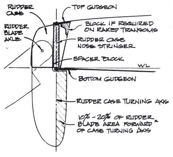
Imagine a profile view of the rudder (or look at the drawing below), and a line drawn through the center of the pivot points on which the case and rudder rotates. The underwater portion of the rudder extending ahead of this axis balances the torque exerted by the underwater portion lying aft of the axis.
We have had success placing 10% to 20% of the underwater rudder blade profile ahead of the projected turning axis. The axis should be as near to plumb (perpendicular to the waterline) as possible. The further from plumb, the more drag is generated with less turning force. Achieving a plumb rotating axis is more difficult when the rudder is mounted on a reverse transom or a conventionally raked transom. On reversed transoms, for example, we have blocked the upper gudgeon to get the axis as plumb as possible. Consider these features when you lay out the rudder case and blade. A block at the bottom inner edge of the case stops the forward rotation of the rudder. Some tuning of the rudder’s balance can be made by adjusting the thickness of the block.
Building the inner skin
If your rudder blade is not already built, you must at least know the dimensions it will be before proceeding with the rudder case. A rudder blade’s thickness is determined by the size and weight of the craft and, as mentioned in the Fall 1992 EPOXYWORKS article, the foil section desired. A retractable rudder blade such as this does not have a foil shape in the case area but is squared off.
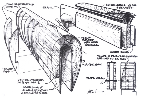
Make an accurate substitute or blank, the exact thickness as the top end of the rudder blade, about a foot longer than the case. Round the leading edge of the blank to serve as a mold to build the inner skin of the case.
To build the inner sides of the case, begin by cutting two pieces of 1/4″ plywood that represent the profile shape of the case from a tangent to the leading edge radius. Orient the face grain of the plywood perpendicular to the waterline. Bond a layer of 6 oz. fabric to the sides of the plywood that will become the inner sides of the case, and apply several coats of epoxy/423 graphite to fill the weave of the cloth and provide a smooth abrasion-resistant surface.
Bevel the outside forward edge of these inner skins to an 8:1 slope. The bevel will be the bonding area for the nose of the inner skin. Before building the nose of the inner skin and the rest of the rudder case over the blank, cover the blank with two layers of 6 mil plastic to prevent inadvertent bonding. The plastic also provides the necessary clearance between the blade and the case for all to work smoothly. Assembly will be easier with one end of the blank held firmly in a bench vice (leading edge up). Clamp the inner skin sides in position on the plastic-covered blank. The forward edge of the bevel should meet the point where the nose begins to curve.
Laminate alternating layers of biaxial glass fabric and carbon fiber over the rounded blank and onto the beveled portion of the inner skins. Four layers of glass with three of 701 graphite should do for this particular case. Between layers of glass, the 1″ wide graphite tows lay edge to edge, parallel with the waterline. The glass and graphite lay-up can extend beyond the beveled area but should not end short. When the graphite and fiberglass are in place and thoroughly wetted with epoxy, lay two layers of release fabric over the laminate. Smooth out the lay-up firmly with your gloved hand to eliminate any air pockets and squeeze out excess epoxy from the laminate.
Adding spars
After the epoxy cures, remove the release fabric and bond the full-length mid-spars onto the outer surface of the inner skins. These clear fir or mahogany spars should be <$E3/4>” thick by 2″ wide. Center the mid-spars over the axle location. The axle should be more or less centered between the cases’ leading and trailing edges. Its height should be about half the blade’s fore/aft dimension.
The forward stringer should be 1<$E1/2>” thick (fore and aft) and as wide as the thickness of the blade, plus the total thickness of the inner skins. This bonds directly to the rounded part of the fiberglass laminate. Use plenty of WEST SYSTEM® Epoxy thickened with 406 Colloidal Silica filler to bridge the gap between the spar and the rounded surface. When cured, plane the forward edge of the nose stringer so the round equals the radius of the case.
Adding ribs and core material
Make a cardboard pattern that fits over the inner skin and spars, and describes the outer shape of the case from the nose stringer to the trailing edge of the inner skin. Fabricate 1/4″-thick plywood ribs from the cardboard pattern to fit over the mid-spars and the nose stringer. Space the ribs 2 inches apart, but double up the two ribs at the top and bottom of the case. Bond the ribs in place with epoxy/406 filler. After the epoxy cures, cut blocks of honeycomb or urethane foam core material to fit between the ribs of the case. Wet out all inner surfaces of the inner skin, ribs, and stringers and bond the core material in place with epoxy/406 filler. When the epoxy has cured, shape the case profile and fair the core material and ribs to the desired final form.
The outer skin
In this case, the outer skin is composed of 4 layers of 738 Biaxial Fabric (with mat backing) and an outer layer of 742 Glass Fabric (6 oz. woven). Cut the fabric to shape slightly oversized. Wet out the surface of the core, ribs, and nose stringer and lay the wet-out fabric over the case. Cover the lay-up with release fabric and squeegee all excess resin from the laminate. Remove the release fabric after the lay-up has cured, and trim the excess fabric at the top, bottom, and trailing edges of the case.
Raising and lowering the blade
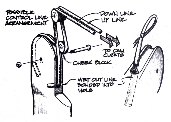
There are a number of ways to raise and lower the blade. Attach the raise and lower lines to the rudder blade, by bonding them into holes drilled about 6 times as deep as the line’s diameter. Tape the line indicating the depth limit. Wet out the line and the hole thoroughly with epoxy. Add some 406 thickened epoxy to the hole and jab the line into the hole. The ‘up’ line passes through a cheek block mounted on the inner surface of the case, then passes through another block at the case top. The line should pass through a fair lead then to a deck cleat. The ‘down’ line is bonded into the leading edge and lays in a routed groove on top of the blade. On larger boats, we may dead-end this line inside the case (if there is room for a block) and gain a two to one advantage by attaching a block to it. The ‘down’ line is then bonded inside the case, through the block and up through a block and the fair lead. This multiplier could also be done on the deck.
Rudder Hardware
Fabricate the rudder pintle and gudgeon fittings from stainless steel. We have had good results with the system illustrated. The pintles are bonded into the rudder case and set into holes machined in the stainless gudgeons. The bottom gudgeon mounting holes are machined for flat head screws and can be permanently bonded to the transom or hull. The top gudgeon is machined with straight holes that slip over permanently bonded studs and held with nuts. If the case has to be removed for service the nuts can be removed and the gudgeon will lift off the top pintle. When the top one is removed the bottom pintle simply lifts out of the hole in the bottom gudgeon.
When designing the hardware, it’s important to mount the plates parallel to each other and perpendicular to the plane of axis. Bond all fasteners with epoxy for long-term reliability. If you need to remove fasteners, heat them with a solder gun.


