Building a Masthead Fitting
Spring 2006

GET STARTED
FREE PRINT & DIGITAL EDITIONS

Spring 2006
Creating a masthead fitting is another use of the lost foam method to produce a custom part with a molded interior cavity. In this case, the part was a masthead fitting to hold an internal sheave and provide a route for the halyard to pass. This method can be adapted to a variety of other applications, as demonstrated in Fabricating an Air Scoop.
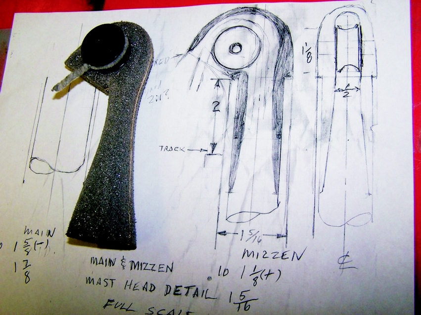
The first step was to make a full-size drawing of the fitting to use as a reference for manufacturing (Photo 1). Using the drawing, I fashioned Styrofoam to represent the fitting’s internal void. I bonded pieces of foam together to produce a billet of sufficient size, using the bond lines for a centerline to aid in measurements. (By using more layers of foam, you could use the additional glue lines each side of the centerline to produce contour lines for additional shaping guides.)
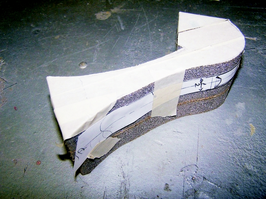
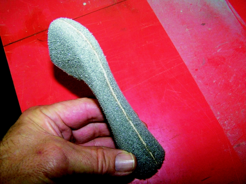
From the drawing, I made templates of the two side views. I taped them to the foam billet so I could rough-out the mold on a bandsaw (Photo 2). Then I rounded over and smoothed the corners with sandpaper (Photo 3). I bonded the sculpted foam blank to a temporary base to facilitate handling and applied paste wax to the mold to fill the porosity of the foam. This was done to produce a smoother surface and promote the release of laminate later on.
Next, I applied a 1/8″ thick layer of WEST SYSTEM® 105/205 epoxy (thickened to a grease-like consistency with 406 Colloidal Silica and 423 Graphite Powder) over the entire part.
I wet out strips of woven graphite fiber reinforcement and pressed them into the thickened mixture until I achieved an estimated thickness of ¼”. (Any more than this could have resulted in excessive exothermic temperatures.) While the laminate was still wet, I covered it with plastic (a freezer bag) and wrapped it with self-amalgamating tape. This consolidated the laminate, extruding excess resin out the bottom. reducing resin content to around 45% resin/55% fiber improves mechanical properties. Then I allowed it to cure.
I removed the cured part from the temporary base and dug out the foam with a carving chisel, hand-held rotary tool (Dremel™), file, and knife. As I approached the wax-covered exterior surface of the mold (now the interior surface of the masthead fitting), the foam fell off, revealing and replicating the sculpted surface.
Then, I applied additional layers of fabric to the masthead fitting. I first applied another thickened epoxy/406/423 layer, which helped span minute surface irregularities. I used braided reinforcing material for these layers, taking care to overlap and align successive layers. The tape was produced by cutting braided sleeve material. With braid, fiber orientation can be adjusted simply by compressing or tensioning the material. I used templates made from the drawing to aid in establishing the finished shape/size. Round templates produced from paper towel core made for accurate sizing of round sections. After achieving the shape I wanted, I allowed the final layers of fabric to cure.
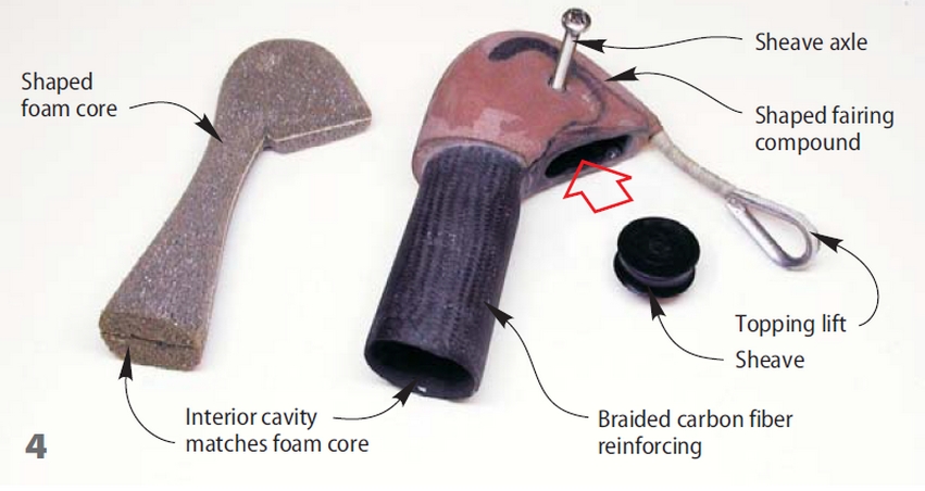
I located the sheave axle hole by measuring off the drawing with calipers. I first drilled undersize to check for accuracy with the real part and then drilled to axle size. You can make the topping lift of various materials; in this instance, I stitched nylon line together and wrapped it with thread for flexibility and lightweight. I bonded the fiber part of the line to the crown of the fitting and covered it with a fairing compound and a layer of braided tape (Photo 4).
A tip for mounting the fitting to the mast: To prevent obstructing the passage with adhesive when the fitting is installed on the top of the mast, I inserted a common balloon covered with a thin layer of Vaseline™ down into the cavity. I inflated it after the fitting was inserted into the masthead, thereby pressing any invading excess adhesive against the spar and out of the way of the halyard. The balloon also exerted sufficient force to prevent any minute movement from the fitting’s intended location until cure-up was achieved. The Vaseline made it easy to remove the deflated balloon after everything had cured.
Final blending and touch-up were done after cure-up, and a cover of carbon fiber braided sock was applied as further reinforcement. After a final coating and sanding, the fitting was primed and painted.


