Tips for Sign Builders & Everyone Else
by Bruce Niederer — GBI Technical Advisor
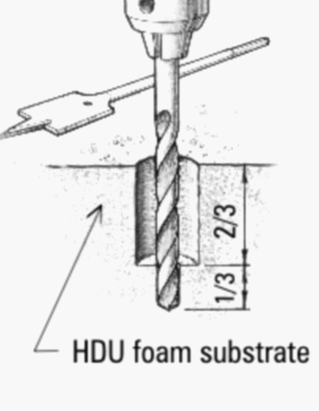
Above: Bonding fasteners in high-density urethane (HDU) foam calls for drilling an oversized hole slightly shallower than the fastener length and setting the fastener in an annulus of thickened epoxy.
Many of our readers who are familiar with WEST SYSTEM® Epoxy products for building and repair already know the benefits of fastener bonding techniques. WEST SYSTEM Epoxy has been used in other industries for many years as well, and these folks apply knowledge and techniques developed in the marine and aerospace industries in their work. A good example is the sign industry, a huge industry in the U.S. with companies ranging from mom & pop garage operations to multimillion-dollar corporations.
The materials used to make signs are as varied as they are to make boats and planes: wood, metal, plastics, composites, and, the focus of this article, high-density urethane (HDU) foam. HDU is used because it is lightweight, easily shaped, and cost-effective. But one of the problems with foam signs, particularly in outdoor applications, is how to attach them to a wall or frame so they stay put through all types of bad weather. The fastener bonding technique developed and recommended by Gougeon Brothers, Inc. for marine hardware using WEST SYSTEM products is perfectly suited to HDU foam sign building.
Fastener Bonding Technique
The basic idea behind the technique is to drill oversized holes in the foam, fill the holes with thickened epoxy, and mount the fasteners in the epoxy. It really is just about that simple, but if that’s all there was to it, this would be a darn short article-so let me elaborate. We have learned from our boatbuilding experience that if a load on a fastener is spread out over a larger surface area than presented by the fastener itself, in any given substrate material, a larger load can be carried. So how can this principle be applied to an HDU foam substrate and why should anyone bother? To answer this question, I wanted to quantify and compare the strength of a fastener bonded with the fastener bonding technique to one that wasn’t. So I set out to devise a few simple experiments.
Identifying the engineering issues, that is, the type of loading the fasteners might experience, was the first step. Visiting some websites, I quickly learned that HDU signs are hung from the back (single or double post or from a wall), from the sides (usually double post), and from the top. This means the fasteners could be loaded in tension, as from top mountings, or in a combination of peel/shear loading, as from back, side or wall mounting. Each type of mounting would also need to withstand durational loading, commonly referred to as creep loading, as well as cyclic and shock loading. These are all typical loads fasteners experience in the marine and aerospace environments
3 KEY ELEMENTS OF FASTENER BONDING STRATEGY
-
Drilling an oversized hole about twice the diameter of the fastener.
- Encapsulating the threads of the fastener in WEST SYSTEM epoxy thickened with 404 High-Density Filler.
- Using a mold release on the threads of the fastener.
THERE ARE SLIGHT DIFFERENCES IN TECHNIQUE BETWEEN BONDING SCREWS AND BOLTS.
For screws, drill an enlarged hole about 2/3 the length of the threads that will be covered in the epoxy. Then drill and center a shallow pilot hole in the bottom of the larger hole. Coat the threads with a mold release (see the sidebar at the end of this article). Mix epoxy filled with 404 High-Density Filler to a catsup consistency, and then pour into the hole, filling it about halfway. Place some of the filled mixture on the threads to avoid trapping air on the threads and then screw it into the pilot hole. This centers the screw in the center of the enlarged hole. Finally, either clean up the excess that squeezes out or add a little more epoxy with a syringe. Allow the epoxy to cure.
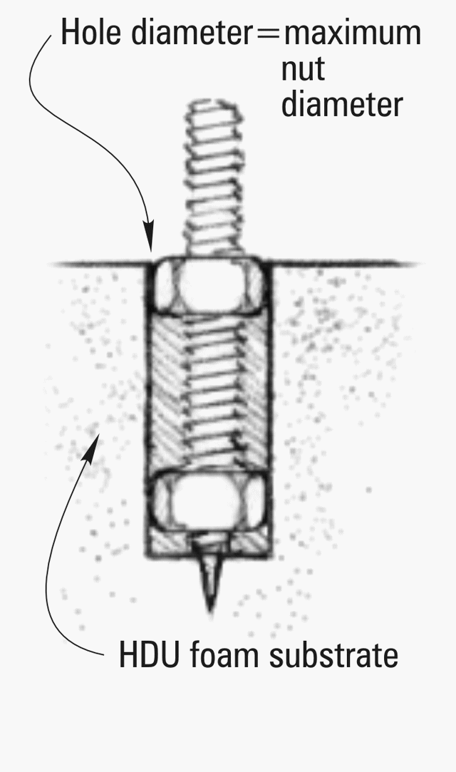
For bolts or threaded rod, the procedure gets modified somewhat. After applying the mold release, place two nuts on the rod-one at the bottom of the threads and one above. This time drill the oversized hole the diameter of the outside points of the nuts. The reason for this is that when the rod and nut assembly is inserted into the hole, it is automatically centered. Additionally, the threaded rod can be turned in and out repeatedly without relying only on molded epoxy threads, which will begin to chip and crack after several cycles in and out. Finally, the top nut is positioned so that its top is just proud of the surface of the foam, so the hardware can be tightened against the nut, not the foam or epoxy. Tightening against the foam or epoxy pre-loads the materials before the loads the fastener is designed to carry are even applied.
The Testing
To begin the testing, I mounted fasteners in 15 pcf (pound/cubic foot-see the sidebar) HDU-a ¼” screw without any epoxy into a properly sized pilot hole and 3/8″ threaded rod with 2 nuts and epoxy as described above. I used our PATTI instrument (Pneumatic Adhesive Tensile Testing Instrument) to pull each fastener to quantify the force needed to remove it from the foam. This test is intended for ASTM Standard D4541, which tests adhesive coatings. To be valid for this application, I calculated the bonding surface described by the area of a cylinder. For the screw, I measured the outside diameter of the threads. The results were dramatic. It took a force of 479 lb to extract the ¾” epoxy annulus and only 143 lb to extract the ¼” screw. What this test is actually testing is the shear strength of the HDU foam itself. The epoxy annulus being larger incorporated more surface area of the foam and so required more than 3 times the force to break a larger area of foam.
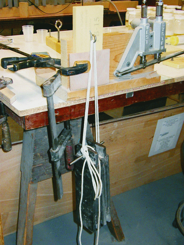
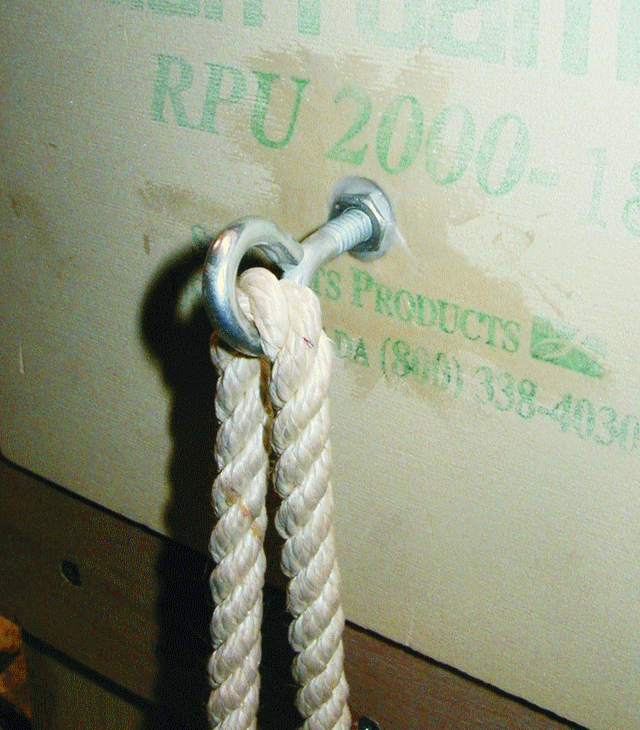
Next, I mounted a 3/16″ eyebolt with 2 nuts in 18 pcf HDU foam as described above. After allowing it to cure 24 hrs, I secured it to a vertical frame and hung weights from it (photo 1). This loaded the fastener in a combination of shear and peel at 90°. This test also incorporates creep into the loading profile. I started with 40 lb for 24 hrs, increased to 60 lb for another 24 hrs, and then to 80 lb for another 24 hrs without any failure. This took the test to quitting time on Friday afternoon, so I just let the test continue over the weekend to see what happened. I returned to a failure on Monday morning, so I don’t know exactly when it failed. But given that a 3/16″ screw eye mounted in a properly sized pilot hole failed immediately when a 40 lb weight was applied (photo 2), the difference in load carrying capacity was dramatic in this application. This technique is well suited to side and back mounting applications.
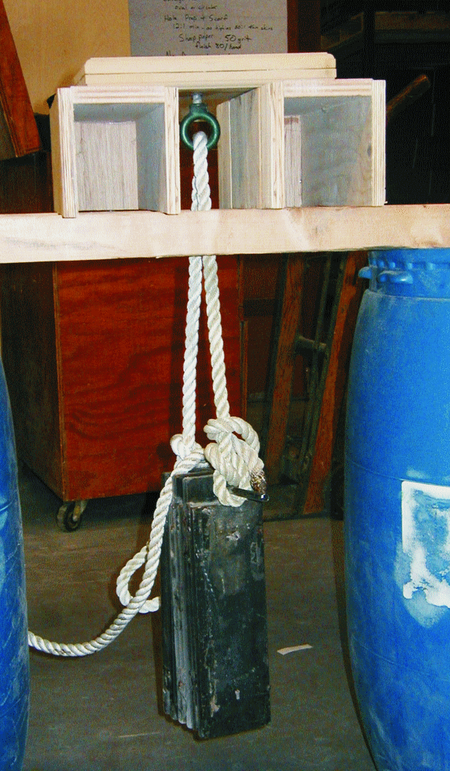
I bonded two pieces of Sign-foam III™ HDU (the density of this foam is unknown, but Sign-foam III is sold only in 10, 15 and 18 pcf) together to form a block of HDU 12″ × 8″ × 1½”. I drilled a 15/16″ hole 1¼” deep in the center of the block to receive a ½” cast eyebolt with 2 nuts. The outside points of the nuts determined the size of the drilled hole. Using a 105/206/404 mixture, I mounted the hardware using the procedure described above. I allowed this to cure for 24 hrs. I then built a support system and hung weights from the eyebolt, beginning with 60 lb (photo 3) and loading the assembly in tension to represent a top-mounted sign. The sample didn’t fail after 24 hrs, so I increased the load to 80 lb and after another 24 hrs to 100 lb. After 72 hrs with the 100 lb load, the sample did not fail.
I then drilled a properly sized pilot hole and inserted a 3/8″ threaded screw into the same block of HDU and ran this set up through the same load scheme. I was quite surprised to learn that the foam held this load and showed no signs of failure. This is quite a testament to the strength and integrity of the Sign- foam III. I decided to press the issue and placed another 20 lb, bringing the total weight to 120 lb. Still no failure. I was beginning to wonder if our technique was necessary. I remembered reading about a sign maker who complained that his top-mounted signs often failed in strong winds, so I decided to test this by swinging the 120 lb of weight side to side. After about 3 back and forth cycles, the fastener pulled free from the foam. Still, this isn’t too shabby given the load of 120 lb. I doubt many foam signs weigh that much. To be fair, I now reloaded the cast eyebolt and hung the same 120 lb from it, and clamped the rope to the eyebolt so the rope wouldn’t simply rotate in the eye. This would force the side loads into the bonded nut assembly. I spent about 10 minutes swinging this assembly pretty vigorously but couldn’t force a failure. I believe that this test showed the advantages of our bonding technique in a “real world” application. And don’t forget-the fastener can be removed and reinserted repeatedly without any damage. The proper pilot hole sample performed quite admirably, but with repeated removals and the cyclic loading from rocking in the wind, it would not perform to the level of a fastener that is bonded in epoxy.
SO WHAT DOES ALL THIS MEAN?
From a practical standpoint, I would say that any sign maker knows that it gets expensive to keep repairing signs that fail in their mountings. The cost savings realized in time and money for repairs makes bonding fasteners with WEST SYSTEM Epoxy a cost-effective alternative.

