Bond Girl’s New Custom Rudder Support
Spring 2023

GET STARTED
FREE PRINT & DIGITAL EDITIONS
Spring 2023
By Jenessa Hilger – GBI Marketing
The weekend before our wedding, my husband and I bought our S2 7.9 meter sailboat. She was exactly what we were looking for, a trailerable racer/cruiser that was a diamond in the rough. Over the past nine years, we’ve made many improvements, the latest of which was building a custom fiberglass and carbon fiber rudder support, or as I nicknamed it, a rudder hook. Read on to see how (and why) we made it.
We felt fate had drawn us to her. She was hull number 7, 007 to be exact, and I had about six months under my belt working at Gougeon Brothers, so the boat basically named herself: Bond Girl. Over the past nine years, we’ve made many improvements, the latest of which was building a custom fiberglass and carbon fiber rudder support, or as I nicknamed it, a rudder hook.
Because of the length of the rudder, and how low these boats sit on the trailer, it’s important to support the rudder kicked up for launching and retrieving. When we purchased the boat, it came with a fabricated stainless steel rod that had hooks on both ends. One end inserted into a lifting eye in the trailing edge of the rudder, and the other would hook onto the vertical wood spacer on the back of the rudder box. The lifting eye in the rudder was susceptible to stress cracking. We tried a few different repairs to reinforce the area, but were never truly satisfied with the results.
Last year, while out for a leisurely afternoon sail, spinnaker flying, with grandparents and kids on board, Bond Girl’s 40-year-old rudder finally had enough. We surveyed the carnage of our poor rudder. It looked like a dead fish floating on the top of the water. The rudder broke at the very top of the blade, right through that problematic liftingeye. We hauled it on board and used the outboard to motor back to the dock.
The immediate problem was that in four days we were scheduled to compete at the Red Fox Regatta in Charlevoix, Michigan. This is our favorite race with the boat, and we didn’t want to let a “little” thing like a rudder keep us from attending. Luckily, a friend loaned us a spare rudder to use until our new one arrived.
The new rudder we ordered through the class arrived mid-winter. While unboxing it, we discovered it had not been pre-drilled for the eye. We seized the opportunity to eliminate the weakness of our previous rudder. The challenge was devising a new fixture to support the rudder securely, with no mechanical attachment point through the rudder itself.
We decided on a concept that would hook like a “J” around the leading edge of the rudder, then run vertically up to the wood spacer on the back of the rudder box, and take a 90˚ turn at the top of the wood to run under the tiller bolt and between the cheek plates. This device would be locked into place with a vertical pin running perpendicular to the tiller bolt. To prevent wear, on the rudder we wanted to use 1/2″ thick roll foam to pad any part of the fixture that would touch the rudder.
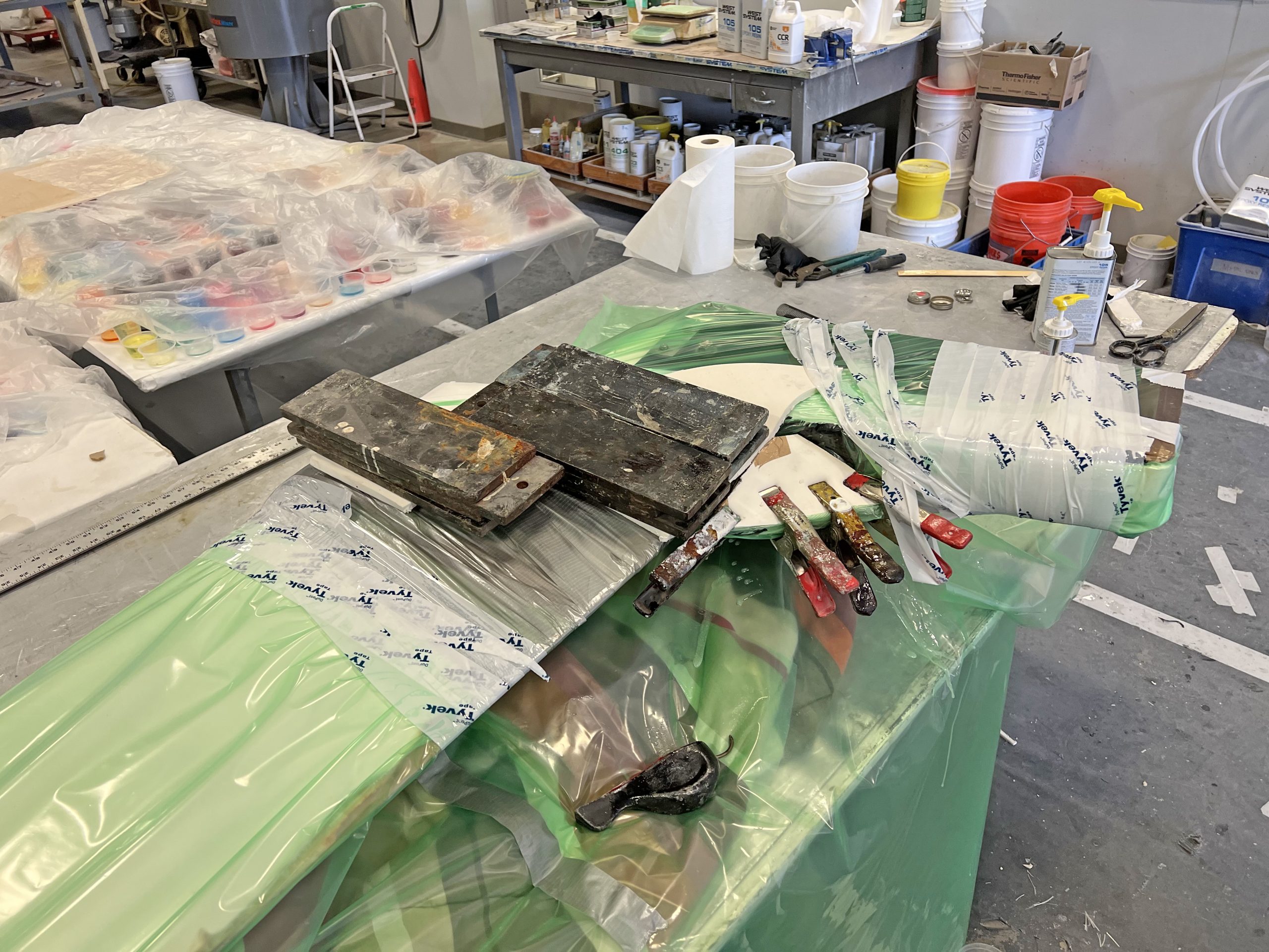
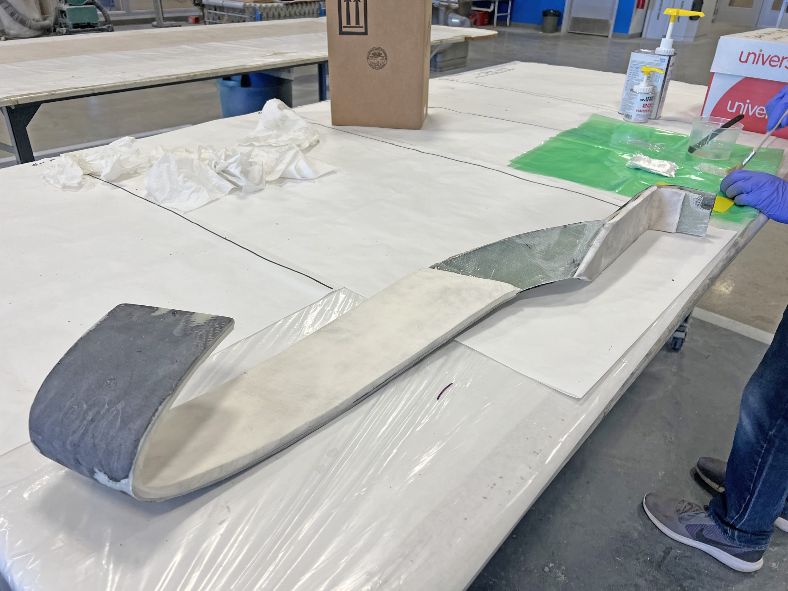
To create this highly custom design, we needed to use the borrowed rudder and our rudder box as a mold to create the perfect fit. We positioned the rudder at the correct angle for pulling the boat out of the water. Then we laid out pieces of our foam and fiberglass to get a feel for where we wanted the hook to be. We also determined where we were going to support and clamp everything once it was wet out with epoxy. The transition between the rudder and the rudder box would need additional support. We determined sandwiching that area with some scraps of foam left over from padding would be sufficient support. Satisfied with our plan, it was time to begin the epoxy work. We masked just about every inch of the rudder to be certain no stray epoxy accidentally got where it shouldn’t be.
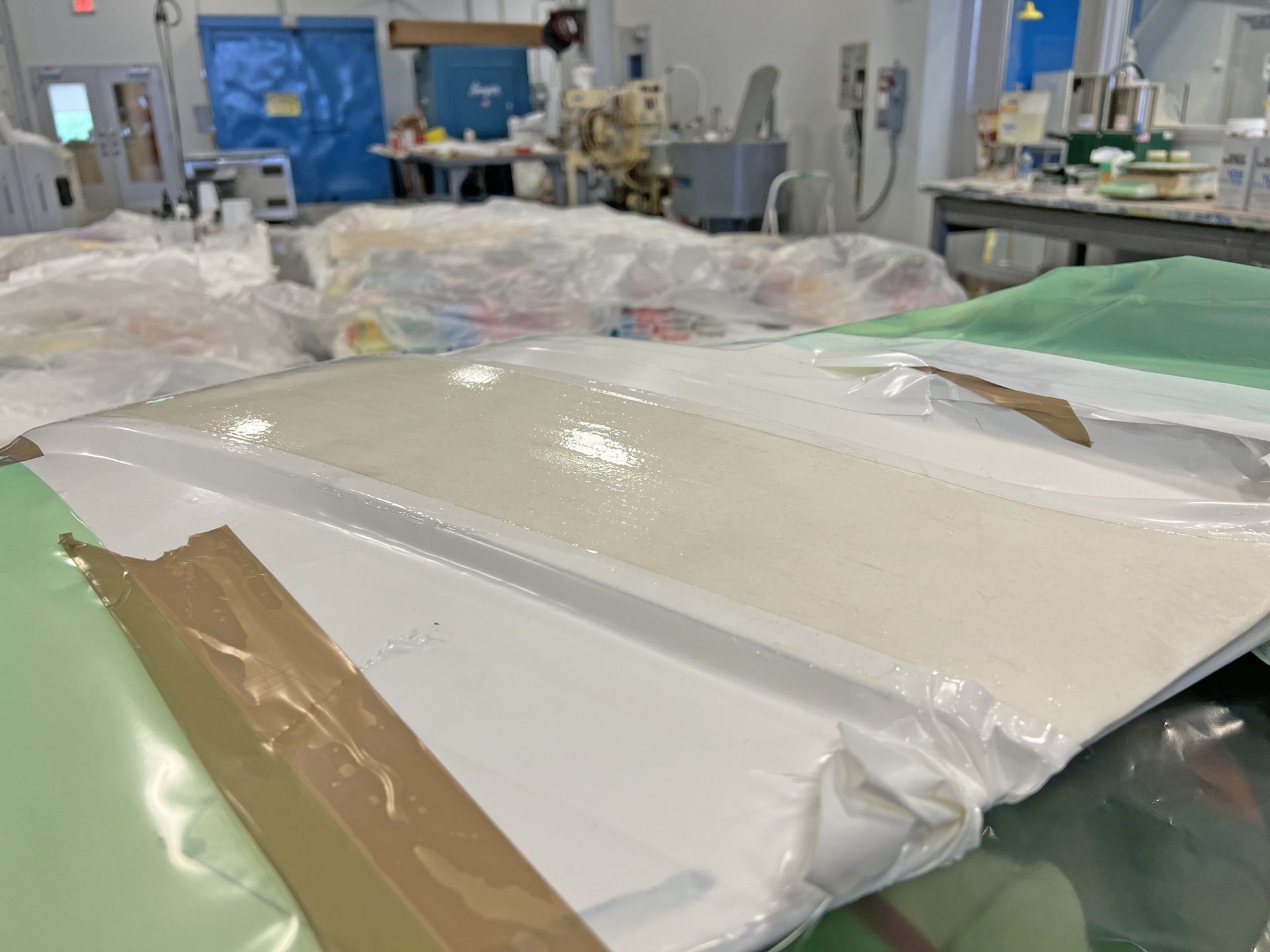
We cut the glass and foam to size, intentionally leaving about an inch margin on all sides to be trimmed off later. Oversizing the materials ensured the full laminate thickness continued all the way to the edge of the final part for maximum strength. The first layer applied to our masked rudder was the ½” foam. The foam was springy and wanted to lift off the rudder, so we taped the edges down to get a tight fit (figure 1). We brushed a light layer of WEST SYSTEM® 105 Epoxy Resin® and 206 Slow Hardener® on the top of the foam. Applying the epoxy directly to the foam did two things: Created better adhesion to the fiberglass, and it kept the foam from drawing epoxy out of the laminate, which could make the finished laminate weaker.
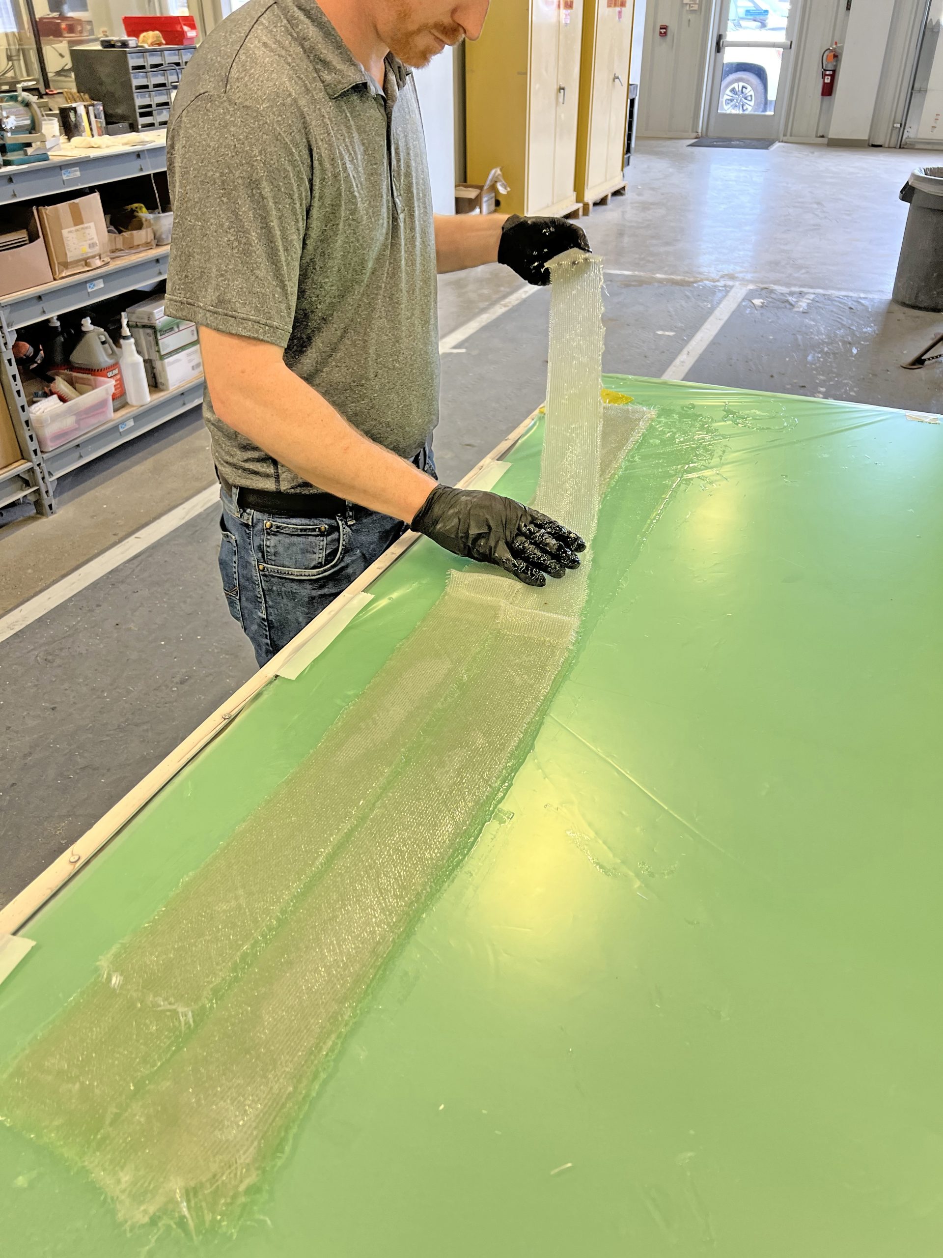
Next, we needed to wet out the 737 Biaxial Fiberglass Tape (17 oz.) on a flat surface, using more 105/206 (figure 2). We wanted to be sure each layer was fully saturated, which is much easier to do on a flat table than on the underside of the rudder. Why use fiberglass tape you ask? Even though we needed a broader surface area where the hook would cradle the rudder, as we transitioned up to the rudder box, the glass would need to taper down to the exact width of our fiberglass tape. The strips of tape would allow us to “weave” them together, tapering down to the single width dimension we needed. This method of weaving would also help evenly transfer the load down the length of the fibers, giving a stronger result than simply
cutting away the unnecessary portion. (It’s also less wasteful).
In total, we were going to need 6 layers of the tape, two strips wide (a total of 12 lengths). We wet out the first two strips of fiberglass tape side by side, followed by all the subsequent layers stacked directly on top of those. Then we folded all but one length of fiberglass back on itself, about 2/3 of the way down the length of the fiberglass. Here we began to “weave” the layers together.
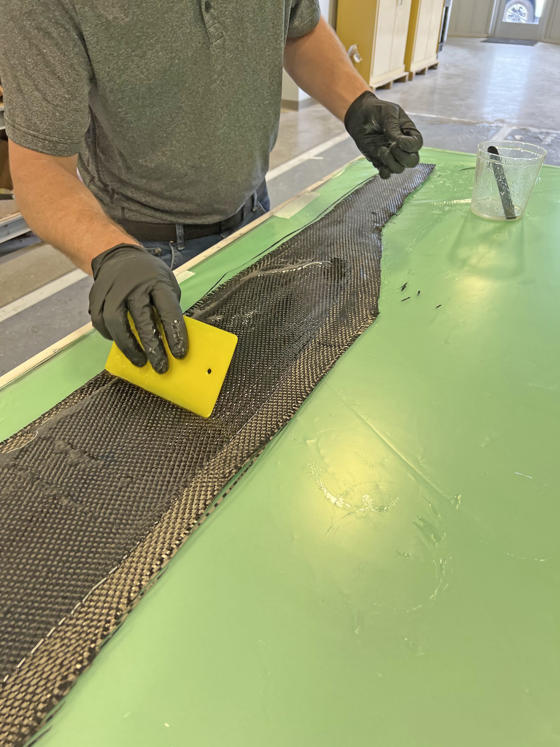
With the first strip left in its original position, we took the strip that was wet out next to it and crossed over the top of the first so that the two ends were on top of one another. Then we moved to the next layer. Again, the first strip was laid back down straight and the second crossed over with the end on top of the others. This continued for the remaining layers. Then we trimmed away some of the excess carbon fiber so it roughly resembled the shape of the fiberglass (figure 3). We wet this out with our epoxy too.
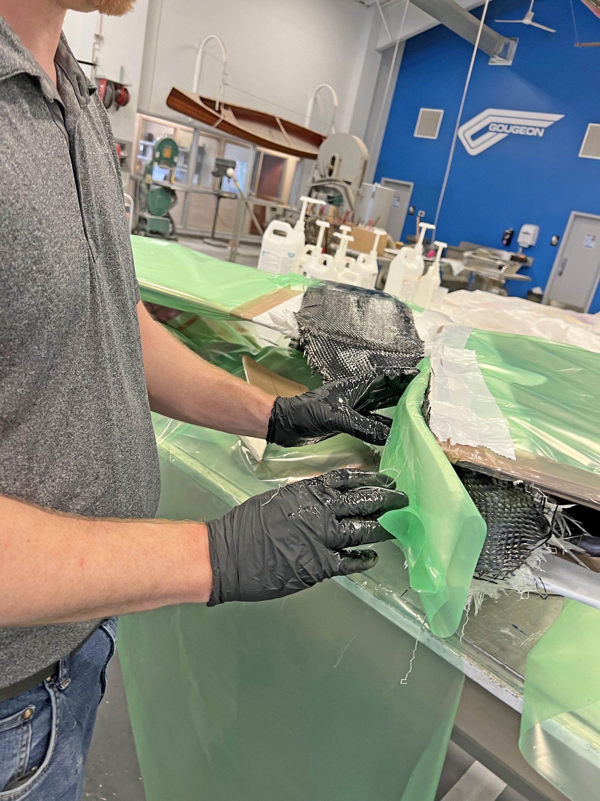
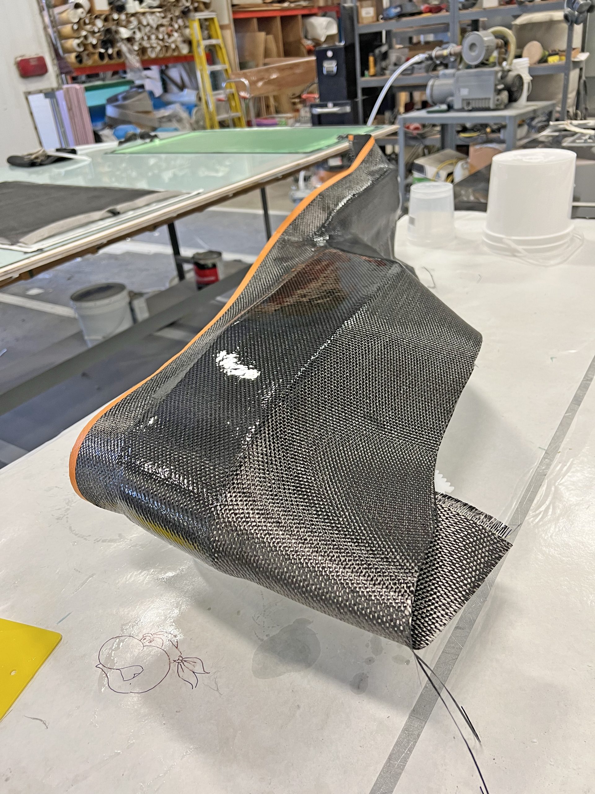
Now it was time to transfer all those heavy, saturated layers to the rudder. Carrying the laminate conjured the feeling of holding a python. Even the texture of the coarse weave carbon was reminiscent of scales to my gloved fingers. We laid the double width section of the laminate on the rudder blade, the single width section on the wood of the rudder box, and the transition section was suspended in between.
The saturated laminate was heavier than we had expected, creating more difficulties positioning the laminate than we originally anticipated. We anchored the single width section to the rudder box first. We laid a piece of release film on top of the laminate. Then, using tape, we encircled the box and laminate, compressing the laminate tightly. Securing this point allowed us to keep tension on the laminate. This was important because the transition from the box to the rudder did not have a ridged support, so it was sagging more than expected under the weight of the wet out laminate.
Under firm tension, we wrapped the double-width end of the laminate around the leading edge of the rudder. We used our tape wrapping method again to evenly clamp the laminate to the rudder.
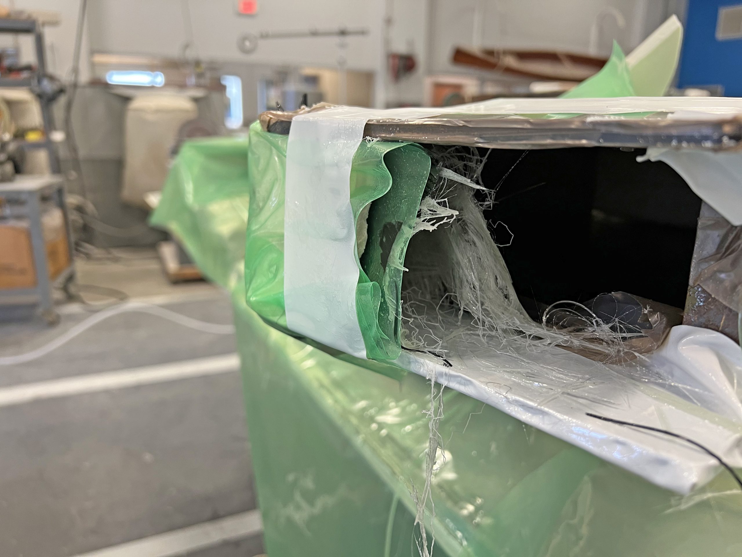
Despite our best efforts to keep the laminate taut, the transition section was still sagging more than we liked. For support, we used scraps of the foam that were covered in mold release tape. We sandwiched the laminate with these, compressed by a couple of spring clamps. The foam helped smooth out the arc of the laminate to a gentler curve without creating hard transition points. Plus, the foam helped cushion and distribute the force applied by the spring clamps holding it together (figure 5).
At this point, the epoxy was kicking off, so we needed to wrap things up. The last section to position was the bend at the tiller pin. The span between the wood of the rudder box and the pin was not wide enough to feed all 13 layers of laminate underneath it. Instead, we split the laminate so 7 layers went below the pin and 6 went above (figure 6). Our reasoning was, if this proved to be a weak area when the epoxy cured, we could easily add reinforcing layers once we separated the part from the rudder. That section would be more accessible. Trying to fit our hands into the small cavity was proving difficult, and we were running out of time. The epoxy was curing.
It was back to the tape again. We continued securing any areas we thought may be too proud or had the possibility of sagging. We also added a few weights for good measure.
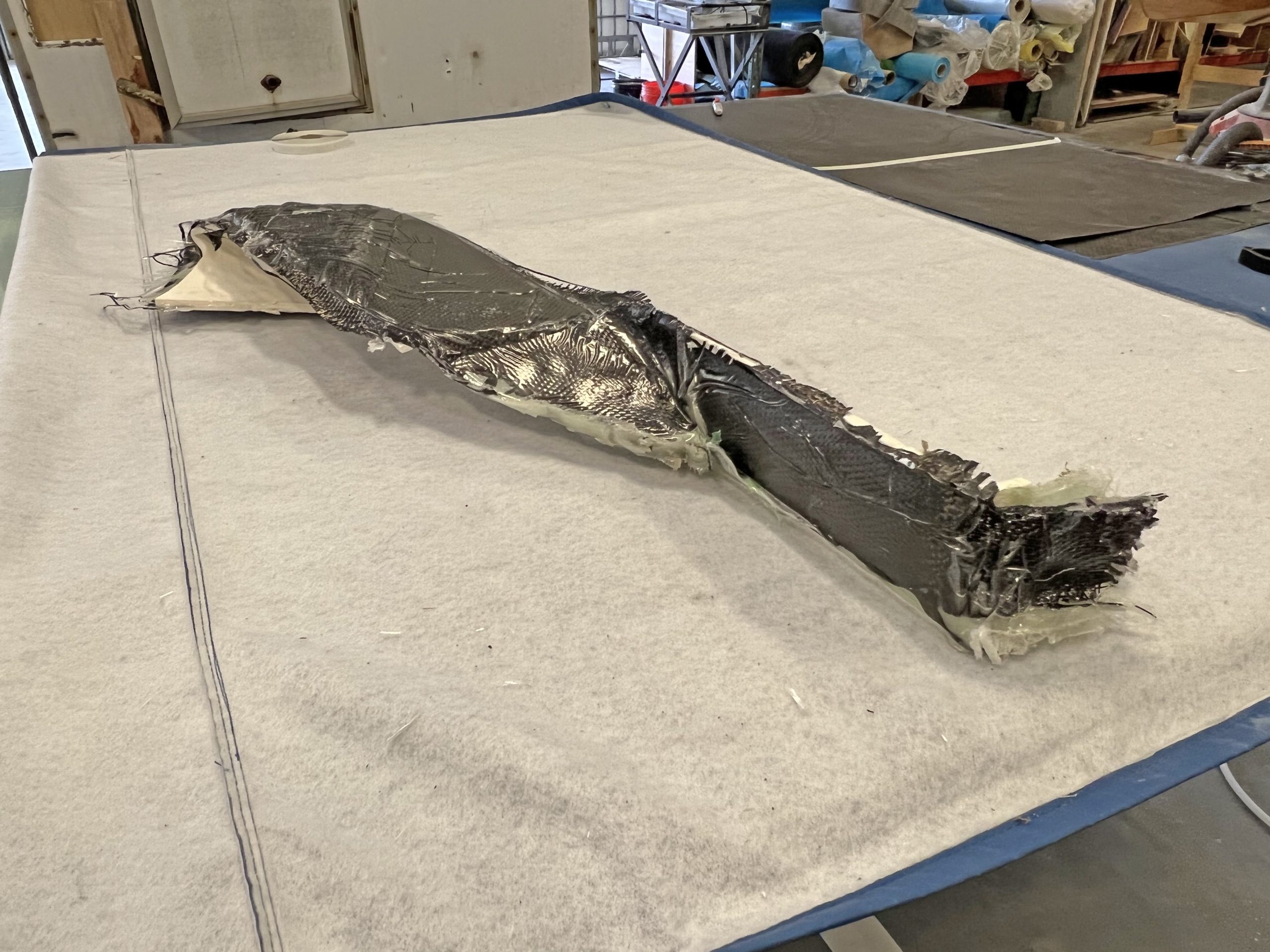
Once the part was cured and demolded, we inspected our work. Not terrible, but definitely room for improvement. The pressure from the tape left some uneven banding and many wrinkles in the part’s surface. Not great from a cosmetic standpoint, however, the laminate was as strong as we had hoped for (figure 7).
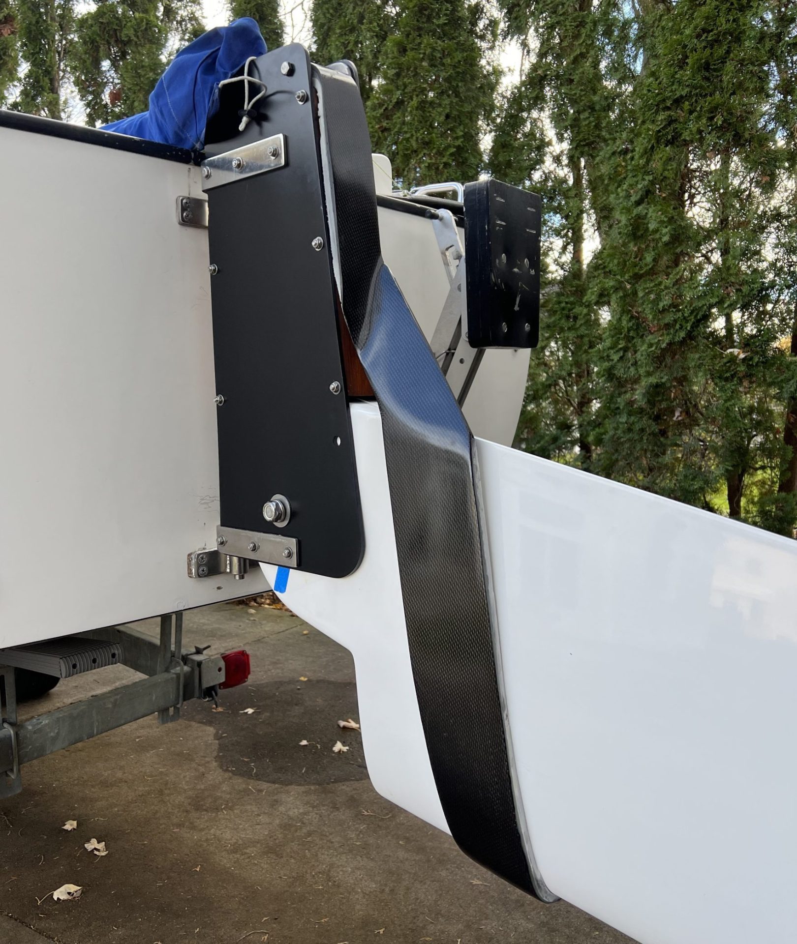
We trimmed the extra material from the edges and did a quick test fit. It functioned better than we had guessed. Because we made the mid-epoxying decision to split the layers around the tiller bolt, the excess epoxy squeezed out on the inboard side of the bolt. This left a little bump on the top and bottom between the laminate split. The resulting effect was that the hook snapped into place around the tiller bolt.
Now it was time to do something about those cosmetics. Our approach was to create a filler layer to even out some of the wrinkles so we minimized grinding into the laminate fibers, and weakening the part. We used 105/206 thickened with 406 Colloidal Silica Filler to it to reach the consistency we were looking for. We also added some 502 Black Pigment to help this fill layer blend in with the carbon fiber (figure 8). Once this frosting layer had cured, we came back with some 80-grit to prep the surface (figure 9).

One more layer of carbon fiber was applied to give us the beautiful aesthetics we were looking for (the added strength wouldn’t hurt either) (figure 10). The part underwent one final trim to clean up the edges, and our pièce de résistance was complete.
If I were to repeat this project, I would have paid closer attention to the tape’s tension while applying it. We were inconsistent with our tension when we were problem solving on the fly, so some wraps were pulled more tightly than others. This caused the release film that was laid on top of the laminate to wrinkle, imprinting the part, and resulting in more finish work. Also, we were running out of tape left and right, so we were grabbing any roll that was handy. Using this hodge podge assortment of tapes, each one could have applied different pressure depending on their width, adhesive, and the material’s stretchiness. I definitely should have been sure to have all the materials I needed at hand before starting to mix the epoxy.
Having gone through the process, I now know that I should have applied the carbon fiber layer after the fiberglass had cured. If I had been more realistic (honest) with myself that there would be imperfections after the initial layup, then I would have planned on applying a thickened coat to address the surface imperfections before applying the highly visible outermost layer.
The resulting rudder hook looks pretty darn racy for the old girl, but with a name like Bond Girl, she deserves nothing less than beautiful epoxy work. I can’t wait to do some durability and ease of use testing over the summer as we compete in our regattas. That will be the true gauge for our success.


