

Building a competitive model rocket
By Brad Parker
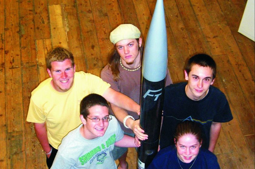
The 2006 NASA Student Launch Initiative (SLI) began for the Flying Tigers, a competitive model rocket club at Caro High School, Michigan, when we accepted the 13th place award in the 2005 Team America Rocketry Challenge at The Plains, Virginia. At that point, we had no idea what we were getting ourselves into. Approximately six months, and thousands of dollars and work hours later, we enjoyed the products of our labor with a perfect flight into the blue Tennessee sky.
As qualifiers for SLI, we competed with other schools to design and construct a reusable rocket to reach an altitude of one mile and carry a scientific payload. In 2006, eleven teams, chosen from over 750 around the country, took part. We were one of six new teams, with five returning veteran teams. Team members included senior Richard Lester, and juniors Brett Cockerill, James Roesner, Kyle Smith, and myself. SLI participants are granted $2500 to aid in the construction of the rocket. It was up to us to raise the remaining funds. The final cost for the project was around $3500.
Designing a reusable model rocket that would fly a mile high was easy. We realized that high-performance composites would provide the best combination of weight, strength, and stiffness necessary for this project. The use of epoxy for the body tube laminates, for coating the plywood bulkheads and fins, and for gluing all the components together would provide the reliable, reusable launch vehicle described in the SLI requirements. We used Gougeon Brothers epoxy throughout the entire construction, which took place in the Gougeon Brothers boat shop. When construction was completed, the rocket was 100″ long, with a tube diameter of 5″ and a fin span of 17″. It weighed 421 oz with everything except the engine.
Dreaming up and implementing the scientific payload was much more difficult. About a week and a half before our proposal was due, we decided that our experiment would measure the levels of greenhouse gasses in the lower levels of the atmosphere. We would then compare our results to those of previous years, listed on an EPA website, to determine if there was a correlation between the concentration of the gasses and the size and strength of hurricanes in the Gulf area. Our actual payload consisted of two altimeters, for parachute deployment and to provide altitude data to go along with our gas concentration data; an iTX multi-gas sensor with data logger, which would provide the gas concentration information; and a wireless video camera.
Making a model rocket mold
It took a few months for construction to actually begin. When we were finally caught up on the reports and fund-raising, we discovered we had a problem. Our designs and simulations called for laminated carbon fiber and fiberglass tubes with an outer diameter of 5″. Pre-fabricated tubes were not readily available, so we decided to make our own tubes. We spent weeks searching for PVC tubing, cardboard shipping tubes for carpet and fiberglass, and anything else that happened to be cylindrical and anywhere near 5″ in diameter that we could use as a mold. It was beginning to look hopeless until we found that the inside diameter of a cardboard tube used to ship Episize™ fiberglass was exactly 5″. Then we had to find material to make the mandrels out of. We began experimenting with spray-foam insulation, with poor results. None of the products we tried was dense enough, and each created a rough, porous surface. When it began to look like we were running out of options yet again, we discovered a water-soluble, plaster-like material from Advanced Ceramics Research, Inc. (ACR). They were kind enough to provide their product at a student discount.
From then on, building the mandrels was simple. We split the cardboard shipping tube down the middle to make the mold for the cast mandrel. We coated the inside with packing tape and a layer of mold release and sealed off one end of our female mold with packing tape. We then placed 2.5″ diameter PVC pipes running the length of the molds in the center for support and to provide us with a handle when wetting out the composites. Next, we simply added water to the powder from ACR and poured the mixture into our molds. The next day, we took our plaster mandrels out of the casting mold, gave them a quick sanding, and coated them with waterproofing sealant, also from ACR. Our mandrels were done.
Laminating the body tubes
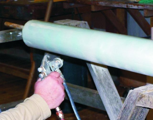
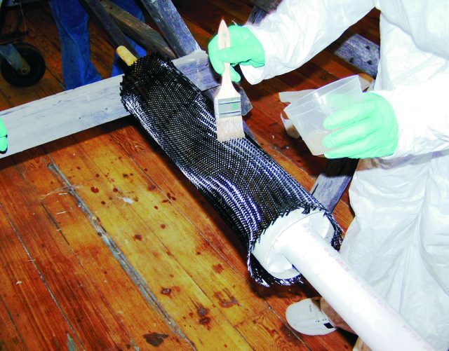
The next step was laminating the body tubes themselves. While some of us were working on the mold/mandrel problem, others had been performing tests to determine the optimum composition for the tubes. An important factor at the time was the drastically increased price of the carbon. So we decided on two layers of fiberglass braid, each with a weight of 13 oz/sq yd, surrounded by one ply of carbon fiber braid with a weight of 11 oz/sq yd (supplied by A&P Technologies, Inc.). In this project, we used braided tubes of carbon and glass as opposed to flat sheets. This was a new experience for all of us and an enjoyable one. The braided tubular cloth was much easier to handle and work with than flat sheets would have been. Wetting out the composites was a simple matter of stretching the material over the mandrel, taping it to prevent slipping, applying the epoxy, and then wrapping the whole thing tightly in nylon 879 Release Fabric. We did that for three nights in a row, the first two layers with fiberglass and the third with carbon.
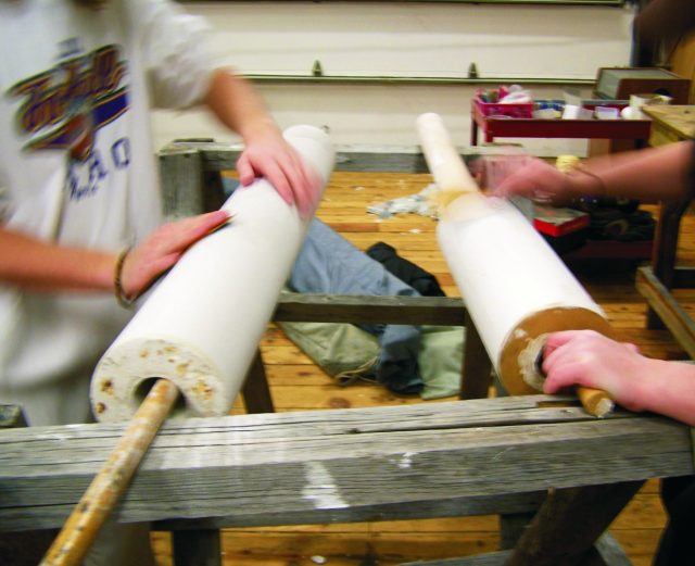
Once the tubes were cured, we soaked the smaller sections in the bathtub at a team member’s house and took the larger ones to the local car wash. After a few hours of soaking or determined spraying with a pressure washer, the mandrel material washed out, leaving us with nearly perfect tubes. To make sure the inside was completely smooth, we attached a flap wheel on an extension to a battery drill and gave the inside a good sanding. The tubes were now done except for the finishing work.
Shaping the fins and building the model rocket couplers
Our next steps in the model rocket project were done simultaneously. Some team members worked on shaping the fins, while others worked on building the couplers that would join the three sections of body tube together. We began work on the fins by simply cutting the basic shape out of ½” plywood. From there, we cut in the notches to allow the fins to be placed inside slots in the lower body tube. Then we shaped the fins with rounded leading edges and pointed tips. We roughed in the shape with the belt sander and then finished with a file and hand sanding. Finally, we coated the fins with epoxy.
We wet out the fiberglass for the couplers inside the cardboard tubes we had used as molds for the mandrels, making the outer diameter of the coupler tubes almost exactly the same as the inner diameter of the body tubes. We made the couplers out of 3 layers of 9 oz/sq yd fiberglass tape.
Assembly
Attaching the fins to the lower tube section and securing one end of each coupler to the body tubes were the two final structural steps in constructing the rocket body. To ensure proper fin alignment on the tubes, we built two plywood jigs that would hold the four fins against the engine mount tube. The engine mount was a 75mm (2.95″) cardboard tube that would keep the engine in place within the main body tube. It was kept centered by a series of 3 plywood centering rings as well as the main bulkheads at the top and bottom of the lower section. Once the fins were properly aligned in the jig, we secured them to the engine mount with epoxy fillets. Later we secured them to the main body tube with more fillets.
The rocket was designed to break into three sections during its descent to allow for the deployment of the parachutes. To that end, we built the couplers, but now one end of each had to be attached to the middle body tube section, known as the e-bay because this housed the electronics as well as the CO2 parachute deployment system. To do this, we taped out the section we didn’t want connected and coated it with mold release. We then covered the other end with epoxy and slid it inside the body tube. This was done at each end of the e-bay. When the epoxy had cured, the body was almost entirely done.
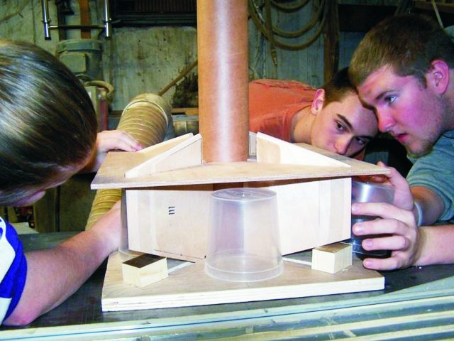
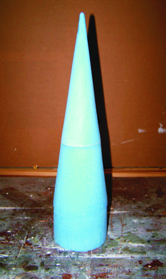
The model rocket nosecone
Finally, we needed a nosecone for our model rocket. Like everything else on the rocket, it had to be hand made because it wasn’t possible to buy parts to fit our unique design. Our mentor from the National Association of Rocketry, Gordon Agnello, helped us on this stage of the build with the use of the lathe in his garage. We formed the shape of the nosecone out of the foam on the lathe and then covered it with 3 layers of fiberglass wetted out with epoxy. When that cured, we gave it a quick sanding and fairing, and the nose cone was ready to be attached to the body.
Finishing
With the nosecone, fins, and couplers assembled, it was time for the finishing touches. We applied a few more coats of epoxy to the tubes to give the carbon fiber a high-gloss finish and applied a metallic silver paint to the nose cone and fins. Finally, we attached the big Flying Tigers decal at the base of the nose as well as the decals of our sponsors.
Then we could sit back for a few minutes before packing for the next morning’s flight to Huntsville, Alabama. In Huntsville, we spent several days touring the Marshall Space Flight Center. Launches of each of the 11 rockets built by the SLI teams culminated the week. Our rocket was one of the largest and highest-powered. The launch itself was perfect, creating an impressive visual and auditory spectacle. We completed the experiment as designed and submitted the final reports to our NASA mentors. The rocket project was a fantastic and fun learning experience. The hands-on nature of the project let us apply our skills in math, physics, and fabrication. We learned how to work with composites and epoxy as well as how to communicate our design and the results of our experiment. We collaborated to work as a team. Lastly, we had the opportunity to travel to NASA’s Marshall Space Flight Center and watch the rocket we had built climb into the sky.


