
By Captain James R. Watson
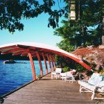
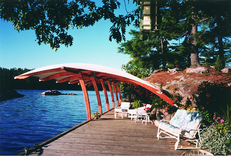
Steve Taylor of Steve Taylor-Builder, Inc., contacted us before undertaking a rather interesting project. He was about to build a boat shelter on an island in the St. Lawrence River. The design called for a row of curved laminated wooden struts, or columns, supporting curved laminated tapered beams that would cantilever over the boat. The 25′ tall, 60′ wide structure would support a weatherproof fabric that would shelter both the dock and the boat.
Steve has built many high quality projects, but had limited experience in laminating. He asked the Gougeon Tech Staff to help him plan the laminating tasks this project required. The Tech Staff responded by devising ways for him to modify boatbuilding techniques for the architectural fabrication.
Steve wanted to know how many laminations or layers should be used. Laminates offer an advantage over solid material in that they randomly spread the flaws inherent in wood. More layers of thinner material are easier to bend. However, too many layers will drive up costs in several ways. They result in more machining scrap, require more handling, and more gluing area. Also, with too many layers, the stock becomes so thin that achieving even clamping pressure becomes more difficult.
Fewer layers of thicker material can result in spring back, or a relaxation of the curve of the laminate. Thicker pieces of wood also increase the chances of dimensional changes due to too much cross sectional mass. For this project, we felt each layer should be no thicker than 1″. This meant eight layers for the columns and thirteen for the beams.
Choosing a wood species
Steve inquired about building the structure of white oak. Bonding white oak is always a little bit of a challenge no matter what adhesive is used. Better choices for a project such as this would be mahogany and Douglas fir. Both are pretty durable, dimensionally stable and look good when naturally finished. You can achieve a very attractive contrast by alternating light and dark colored wood species like fir and mahogany. He chose Honduras mahogany for this project.
Scarffing and tapering
The available mahogany stock was not long enough to make the 25′ beams, so scarffing was inevitable. The first step was to bond shorter lengths together with 8:1 scarf joints to make thirteen full-length boards for each beam. The joints in each layer were staggered to avoid joints near each other in successive layers.
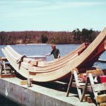
The beams were tapered in profile, and it is tough to taper a laminate with saws and planes. We suggested that they taper the individual laminate layers before laminating. That way, after gluing the layers together, only the sides of the beams would need to be planed. The resulting beams with their tapered layers would also be more aesthetically pleasing. In addition, less end grain would be exposed than if the top or bottom of the beam were sawn to shape after lay-up.
To taper the beams in this manner, Steve and his crew first had to figure the amount of taper in each board, from the thicker cross section in the middle, to the thinner sections at the ends. Next, they made a mirror-opposite master to represent this taper, thicker at the beam’s ends, and thinner at the beam’s middle.
When the master was passed through a thickness planer with a scarfed together board on top of it, the planer removed more material from the ends of the board than the middle. All laminations were passed through a planer in this manner and all were tapered exactly the same.
The logistics of clamping
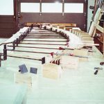
By using the proper clamping jig setup, Steve and his crew were able to laminate each beam in one operation. The same method is used to laminate ring frames for boats. First, they covered their work surface with rigid plastic to prevent inadvertent bonding (soft plastic sheeting can become caught between laminate layers as they are drawn into shape). They described the outer shape of the beam with blocks fixed to a flat table. The thick laminate layers would have to lie straight when placed into the jig, then be forced into the designed curve.
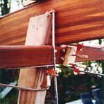
To force the layers into place, they used a series of threaded rods mounted to short sections of angle iron. Each threaded rod ran through a nut welded over a hole in the vertical flange of the angle iron. The threaded rod had a flat pad on the end where it contacted the laminate. A nut welded to the opposite end of the rod allowed the crew to screw it toward the fixed pads describing the outer curve. Air wrenches sped up the process. Once the laminate was pushed into shape, they placed additional clamps as needed along the beam. Only modest pressure was required to draw the parts together and form a tight glue line.
The pictures show the stunning results of Steve Taylor-Builder, Inc.’s first major wood lamination project. After completion, Steve wrote to us and said “I want to thank you for your help and guidance with the tapering and fabricating of the frames, but most of all for your encouragement to do this ourselves. It was great fun and it is very satisfying to know that we can do such things.”