
By Douglas Heckrotte
I first saw outdoor ceiling fans while vacationing on Isla Mujeres, Mexico, just north of Cancun. These fans are ubiquitous and evidently inexpensive. Used both indoors and outdoors, they’re mounted on 3″x 3″ concrete beams. Some of those beams also support sun shades but usually, the fans are completely open to the weather.
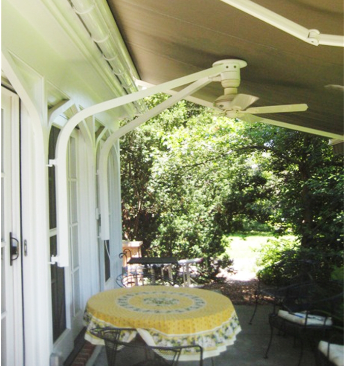
We purchased a waterproof outdoor-rated ceiling fan and for many years used it under the shed roof over our patio. In the course of renovating a summer kitchen and open porch into an all-season summer room, we recently replaced the shed roof with a retractable awning. The outdoor fan makes the open or awning-covered patio very pleasant on beastly hot, airless days.
Here is how I mounted the outdoor ceiling fan, using WEST SYSTEM Epoxy for laminating and coating.
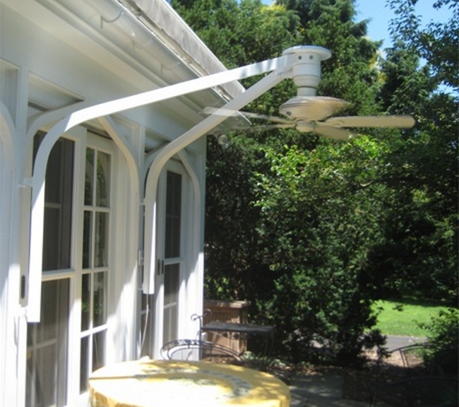
The design constraints were: stay stylistically in keeping with the Gothic trim on our 1857 house; be easily removed for the offseason; conceal wiring; mount the fan adequately; safeguard the awning fabric from chafe, and be long lasting.
I had on hand a quantity of air-dried, rough-sawn American white ash, and several years’ worth of half-used WEST SYSTEM 105 Resin, Hardeners, and Fillers. I used fresh 207 Special Clear Hardener for transparent finishes, limiting the older, hardeners for uses that weren’t appearance-critical.
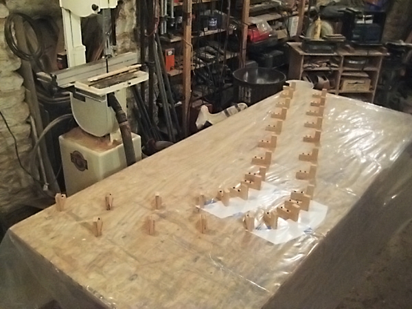
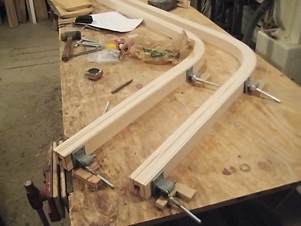
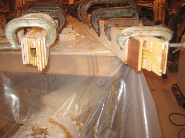
I designed the fan crane on AutoCAD and printed full-size patterns for curves, end angles, and intersections at the hub. I lofted the crane’s legs onto a plywood workbench and included a small amount of camber to account for sagging under the weight of the fan. I didn’t add to the designed curvature to account for springback since the fan would tend to bend the legs in the intended direction. I covered the workbench with poly sheeting and screwed brackets against it for bending and clamping the laminate layups.
I milled the ash lumber into laminae using the least attractive of my stock, usually from the slabs cut near the outside of the log. I collected enough full-length stock for the “face” hub. The milled laminae ended up approximately 3/16″ thick and were made ¼” over width. This meant that I ended up with 12 ash laminae and one 1/16″ thick mahogany veneer. I arranged the random lengths so that the curved portion didn’t have joints, and the joints were staggered throughout the planned layup. I numbered the pieces with chalk.
The 3/16″ ash was too stiff to make the curve, so I had to pre-bend the laminae at the curve. Rather than steam bending, I leaned the wood stock against a short electric baseboard heater and experimented to determine how much time each face of the stock needed to be heated to reach the desired bend. I heated each piece, using a darkroom timer to keep me honest, and popped it into a form to cool. I maintained the stacks of bent laminae in order, and somewhat beyond the required curve until they were laminated.
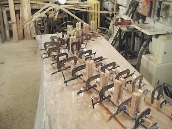
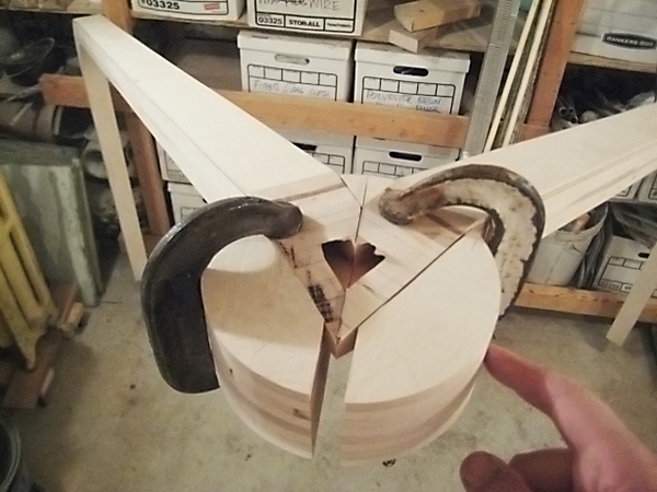
The crane legs are hollow to accommodate the fan’s power cord. I determined that it would be necessary to laminate the inner four laminae, the middle four laminae and the outer five laminae separately. I used the same clamping setup for these six preliminary layups. I cut the middle layups and removed a portion to make way for the wires. Next, I laminated the two narrower layups to the inner layup, then added the outer layup. To set the dimensions and end lengths, I used the lofted drawing that the finished laminations had been done on.
These finished legs were difficult to handle. To be sure of the fit of the fan hub, I made the pintles and hinges and a mockup in my shop.
I laminated scrap ash for the fan hub components and its little “rooflet.” Two of these hub components were fitted and bonded with epoxy onto the top ends of the legs and the remaining three components, with the fan and rooflet, were arranged to be mounted onto the legs/hubs. One bolt suffices for the leg hub connection and a second holds the fan, fan hub, and rooflet assembly in place.
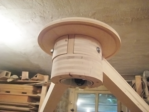
Once all fits were complete, I coated the assemblies with epoxy, allowed it to cure, then sanded and painted them.