by John Holtrop
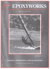
Rigid wing sails offer high aerodynamic efficiency. They have been used in defending the America’s Cup, and are seen on some other high performance catamarans.
Aerodynamically, a rigid wing sail is identical to an airplane wing. Both reward increased lift and decreased drag. However, airplane wings are simple to design since they fly with a fairly constant angle of attack. So an airplane wing’s shape or camber can be optimized for a normal set of flight conditions. Sailboats, on the other hand, must operate under frequently changing conditions. For example, tacking a sailboat forces the airfoil shape of the sail to completely reverse itself, and wind velocity changes require that the sail’s camber and surface area be adjustable.
In the past, rigid wing sails for sailboats used hinged flaps and complex control mechanisms to achieve this flexibility. These designs were heavy, complicated, expensive, and impossible to reef or stow. Obviously, cloth sails are more practical for normal sailboats. Cloth sails are relatively simple and cheap. They can be stretched into many different shapes with simple control lines. For most sailboats, the increased efficiency of a rigid wing is not worth the bother.
A rigid wing sail’s extra efficiency (increased lift and reduced drag) is best utilized on wind surfers, ice boats, land sailors or other high speed applications. The biggest problem is designing a simple, light weight rigid wing sail. Modern composite materials make it possible to combine the efficiency of a rigid wing with the simplicity of a cloth sail.
Thin composite parts will bend easily without cracking, and these are many times stronger and stiffer than the best sail cloth. Thicker sections (solid or cored) can be added at specific locations where stiffness is critical. This allows one part of a composite structure to be rigid, while other areas are flexible. Composite materials (carbon fiber, aramid, honeycomb, foam etc.) can be added to optimize strength, stiffness and weight.
The wing sail concept combines a thick, rigid airfoil nose with a flexible center body and thin trailing edge. The wing sail is molded from composite materials in the form of a symmetrical airfoil. If the wing sail is rotated into the wind slightly, aerodynamic forces buckle the windward side of the flexible center inward and pull the lee side out. These flexible areas then deform smoothly into a shape resembling a conventional cambered rigid airfoil. The amount of camber is controlled by the out haul tension and the stiffness of the materials, just like a cloth sail. When tacking, the flexible surfaces snap over to the other side, and the camber shape is reversed (as with cloth sails). The rigid leading edge is stiff enough to handle all bending loads, eliminating the need for a traditional mast and shrouds.
While the basic concept is simple, the exact shape that the deformed wing sail will take and its efficiency, is difficult to predict without building a prototype.
Some excellent research has been done on flexible airfoils, both single and double sided, with a variety of leading edges. Much of the airfoil theory in the following design was gleaned from an article written by Mark D. Maughmer (Department of Aeronautical and Astronautical Engineering, University of Illinois, Urbana) titled “A comparison of the aerodynamic characteristics of eight sailwing airfoil sections” (#N79-2389, 1972). Mark’s paper predicts at least a 50 percent lift/drag improvement for a thick, double surface airfoil, over a conventional sail/mast combination.
Theories are important, but the real proof is how well a full size operating prototype performs. I selected a wind surfer for the prototype, in order to reduce cost, weight and labor. Three years and many labor-hours later, I finally put the theory to test.
I selected dimensions based on a standard 60-70 sq. ft. wind surfer sail. Since the rigid sail was more efficient, I designed it one-third smaller, for a total of 40 sq. ft.:
- Length 152″
- Max chord (width) 52″
- Head 26″
- Foot 30″
- Maximum thickness 6″
The thickness of an airfoil is usually expressed as a percentage of the chord. For low-speed efficiency, 12 to 18 percent is typical. I selected the lower value, 12 percent, to keep size and weight down. The leading edge shape was taken from a NACA (National Advisory Committee for Aeronautics) #63 cross section, which has a fairly sharp elliptical nose. I basically guessed at these values. They looked reasonable, but other NACA shapes and thicknesses may be more efficient. I attached the wishbone to a piece of tubing glassed into a socket molded behind the leading edge, and laced it to the clew with a four-to-one out haul. Then I bonded a tapered “C” section spar inside of the wing, from head to foot, at the 1/4 chord line. It terminated with a 12 inch tube, which contained a standard BIC sailboard gooseneck fitting. This spar, and the rigid leading edge, carry all of the bending loads and form a watertight chamber, providing several hundred pounds of flotation.
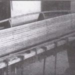
I built up a plug (top photo) from wood strips, and used it as a male mold for the rigid elliptical nose and tapered spar. Next, I attached plywood sides to the base of the plug to form a tear drop cross section. After I filled, sanded, and sealed the plug, I coated it with a fiberglass release film. Then I laid two layers of 60oz fiberglass over the entire plug, adding several extra layers in the nose region.
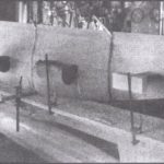
I pulled off the cured part, and glassed foam strips to the inside for increased stiffness. Next I molded a “C” section main spar to fit the plug base, fitted it to the nose (bottom photo), and glassed it into its final position. I added two layers of inch-wide, unidirectional graphite fiber to the spar caps to increase bending stiffness.
I molded the single surface trailing edge, on a flat plywood form, from two layers of 7-ounce Kevlar cloth. The unsupported trailing edge was a little too flexible, so I added three foam battens (1/4″ x1″x18″) to one side, about 24 inches apart. The openings at the head and foot of the double surface section, I filled with foam plugs, rounded, and glassed watertight.
To stress test the finished structure, I stood in the center of the spar while it was supported at both ends. My 190 pounds deflected the wing about half an inch, causing some creaking, but it held. With a fresh coat of paint and fitted with a wishbone and gooseneck, the finished sail weighed 36 pounds. This is 10 to 15 pounds heavier than a conventional rig.
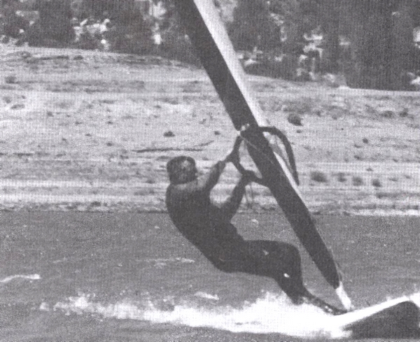
Now for the moment of truth! Three of us trucked my BIC sailboard and the wing sail over to Lake Isabella in Kern County, Calif. Known for good wind, Isabella is a very popular lake for wind surfing. When we arrived, the winds were medium, about 15 knots, with occasional gusts to 20. Everyone was using big sails. The three of us tested the wing sail for the next four hours. We didn’t blow anyone off the lake, but we got a lot of attention and learned a great deal about the design.
Good features
1. The wing was very sensitive to changes in “angle of attack.” It could be feathered easily, then generate lift with just the slightest pull on the wishbone. At speed, the wing seemed to have a narrow “sweet spot,” and the rider could dump power very quickly. This made gusts easy to handle, and was predicted in Mark’s article. His data showed the L/D curve for a double-sided sail to be narrow. The single-sided conventional sail has a flatter L/D curve, and is not as sensitive to small changes in the angle of attack.
2. The wing was much stiffer than a standard rig. There was no “give” during gusts or when pumping. Twist was not excessive, and the trailing edge (leech) was stable and did not flutter.
3. The double surface section responded to air loads very nicely. The deformed shape looked like a “real” airfoil, and could be controlled without out haul tension. Due to the stiffness of the wing, the out haul had to be quite loose to develop the proper amount of camber for this wind condition. This made the wishbone feel sloppy, but did not cause control problems.
4. Speed was only slightly less than other similar wind surfers. During gusts the boat accelerated well, and matched speed with other boats. The general feeling was that our boat was performing well for such a small sail and light wind. Twenty-five knots winds, or a 60 sq. ft. sail,` would have been ideal.
5. The rig floated high in the water and was easy to up haul. We didn’t attempt any water starts, but the wing lifted well, and beach starts were easy.
Undesirable features:
1. The sail area was too small for the wind condition, and we had no easy way to increase it. With the advantage of hindsight, I would design the upper three feet to be removable. A larger than normal sail might work with a wing sail, since it luffs cleanly and very quickly. This would help under strong wind conditions.
2. With the out haul loose for more power, the wishbone felt sloppy. A “slip joint” out haul would hold the wishbone firmly, and still allow for camber adjustment. A one-to-one purchase is adequate, since the wing sail is so rigid.
3. When the wing was dropped, the rigid foot area hit the side of the board. Unlike cloth, the fiberglass would not give, so the foot of the sail ripped about 12 inches. This let water into the center section, but the damage did not get any worse, or effect performance. The foot section needs to be heavier, and padded like most goosenecks.
4. Thirty six pounds is a little too heavy. Using a foam core leading edge and thinner laminates could save five pounds, maybe more. On a larger boat, the extra weight may be offset since halyards, shrouds, turnbuckles, and chain plates are not needed.
5. Visibility behind the wing is poor. Clear windows could be stitched or laced into the sail.
Conclusion
I think these tests show that the basic concept is sound, and practical for some applications. Thick, well shaped, double surface airfoils are more efficient than cloth sails. Composite materials can be designed to deform into a smooth aerodynamic shape under air loads, without complicated flaps, hinges, and control lines. The bending and torsional stiffness in the leading edge is very high, and a free-standing rig is a definite possibility for larger sailboats. The design has a lot of potential for ice boats, sand sailors, and very high speed sailboats.

