The Structural Repair of Wingspread
Spring 1996

GET STARTED
FREE PRINT & DIGITAL EDITIONS
Spring 1996

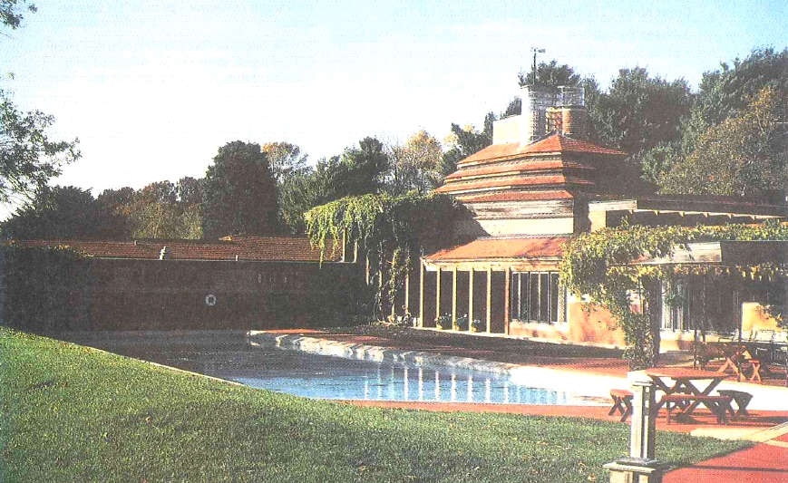
Wingspread, a Frank Lloyd Wright-designed residence near Racine, Wisconsin, was in desperate need of stabilization. The roof and side walls were showing movement and cracks caused by extreme snow loads and previous remodeling. Because this house is on the National Register of Historic Buildings (NRHB), the owners and architects were restricted to stringent guidelines in making repairs.
The NRHB requires that the building’s original architectural details be preserved, that Wright’s design intent be understood, that intervention compliment the original design, and that irreversible structural changes be avoided wherever possible, meaning repairs should be removable at some future date.
By removing the terra-cotta roof tiles and working only from the exterior, the owners could leave interior trim and plaster undisturbed. They wanted to use our epoxy products with fiberglass and carbon fiber to make these repairs on this important Wright building.
Wingspread was built in 1938 for the owner of S. C. Johnson & Son, Inc. With 14,000 square feet of floor space, it is the largest residence Wright designed and built. It is currently used by The Johnson Foundation as a conference center. From the air, the house resembles a pinwheel with four arms radiating from a central great hall.
It was the great hall roof and one of the pinwheel arms, the east wing, that needed repair. The Hillier Group, the project managers, decided to repair the east wing first because this was the more straightforward of the two projects. We at Gougeon Brothers, Inc. did research and provided test information, and Hillier used our epoxy products to do the job.
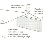
The east wing is essentially a long hallway with a cathedral ceiling that differs from most. In a typical cathedral ceiling, the ridge ends of the rafters rest on a center “ridge beam”—a configuration that allows the weight of the roof to push straight down on the beam and the side walls. However, Wright omitted a ridge beam on the east wing, and instead tied the side walls together with several interior walls, and relied on horizontal beams on top of the exterior walls to resist the roof’s outward push on the top of the walls.
The structural problems in the east wing were the result of a renovation undertaken in the 1940’s, when the owner removed several of the interior walls. This change overloaded the horizontal beams and the walls began to bow outward at the top. To demonstrate this, fold a sheet of paper to look like a roof, set the paper on a table and push down on the peak. As you push down, the “ridge” sags and the bottom edges or eaves (where they would be connected to the tops of the walls) spread apart.
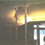
By 1994, the walls had bowed and the roof had sagged so much that the current owners were afraid the roof would collapse. The Johnson Foundation asked Robert Silman Associates of New York City to design and supervise construction of temporary shoring inside the house to hold up the roof, and also to engineer a permanent solution to the problem. Silman assigned to the project John McDonald, a Senior Structural Engineer for their firm.
Tying the walls together with a couple of ceiling joists to check the outward bowing of the walls would have been the simple answer, but the NHRB does not allow altering the structure’s appearance. So Silman and Associates started thinking about other ways to stabilize the structure. They had little choice but to attack the problem from the exterior. The firm came up with the unique approach of installing a rigid shell of fiberglass and carbon fiber on top of the roof sheathing. Stiffening the roof so the eaves cannot deflect outward prevents the walls from bowing. To visualize this, substitute angle iron for the paper roof in the earlier example.
John McDonald had calculated how strong and stiff a membrane would have to be to stop the walls from spreading, but he lacked the information on those characteristics as they applied to fiberglass and carbon fiber. Gougeon Brothers was able to provide some reasonable estimates that enabled Silman to decide if the process was feasible. Later, these estimates were verified by performing a variety of tests.
McDonald’s calculations determined that fiberglass cloth was not stiff enough for use in the highly stressed areas of the roof. Since the ultimate objective was to stabilize the roof and walls, they chose carbon fiber as the reinforcing material in the high-stress areas of the roof. This accounted for about half of the repair area. They would repair the remainder with fiberglass cloth. To best counteract the forces exerted on the roof, they chose a tri-axial carbon fiber fabric with one of the axes running parallel to the ridge and the other two axes at ±45° to the ridge.
Using some preliminary material-strength values provided by Gougeon Brothers, McDonald calculated that the carbon fiber/fiberglass/epoxy membrane needed to be ½” thick in order to provide the requisite stiffness. We suggested the dry weight of the fiberglass and carbon fiber cloth be held to around 20 ounces per square yard to facilitate saturating the cloth with epoxy. In order to obtain a ½” thick layer, 13 layers of 20-ounce carbon fiber were necessary.
Next the engineers needed to figure out how to connect the fiberglass membrane to the rafters. It might seem that since the roof sheathing is nailed to the rafters, simply bonding the membrane to the sheathing would turn the membrane, sheathing and rafters into one stiff unit. However, it is not that simple. All of the stress the membrane is resisting would be transferred to the nails in the sheathing boards (the only attachment of the sheathing to the rafters). Nails are not strong enough to do the job.
Gougeon Brothers, Inc. has been advocating bonding fasteners in epoxy for many years. We suggested drilling an oversize hole through the sheathing into the rafter below, then inserting a large screw into the oversized hole and filling the space around it with epoxy. Doing this dramatically increases the fastener’s pull-out strength and shear strength. John McDonald determined that one #24 flat head wood screw be installed through each sheathing board where it intersects the rafter. I had no idea a screw of that size existed, but shortly thereafter some magically arrived here. We began a testing program to determine exactly how well the method would transfer the loads from the membrane through the sheathing to the rafters.
McDonald and Gougeon Brothers’ Project Engineer, Bill Bertelsen, planned a testing program to determine how much load the bonded fasteners could handle. We built “double shear” test samples, which consisted of a section of Douglas fir 2″x 6″ rafter with a length of 1″x 6″ pine sheathing board attached to each side of the rafter. These tests do not exactly duplicate the construction method used in the house, but were chosen because a symmetrical sample gives the most realistic shear data.
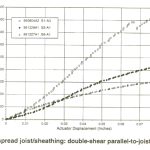
For test purposes, we attached the sheathing boards to the rafter sections in three different configurations:
º = Nailed with 8d common nails, the standard construction technique. (S6-A1)
• = Nailed with 8d nails and additionally, one #24 x 4½” flathead wood screw 3/8″ shank diameter) installed in a proper pilot hole. (S5-A1)
Δ = Nailed and one #24 screw potted in epoxy. (S1-A1)
The tests, plotted on the graph (see gallery below), show the relative shear strength of these three configurations and demonstrate the benefit of epoxy in installing fasteners. Remember this is a double shear test, so the shear strength per side is half the value shown on the graphs.
Most fasteners are weaker in shear than in tension. This is because when loaded sideways they exert extremely high point loading on the surrounding wood. The wood fiber is much softer than the metal fastener. It crushes, allowing the fastener to move laterally. Because epoxy is much harder than wood, bonding a fastener in epoxy improves the crush strength of the wood. Additionally, drilling an oversized hole and filling it with epoxy exposes more frontal area and thereby reduces the point loads on the soft wood fiber.
When exposed to shear loads, small diameter fasteners fail more quickly than large fasteners. The large fastener presents more frontal area, reducing the intensity of the point loads.
The graph above shows how much better a bonded fastener works. Moving the sheathing .03″ (about the width of a pencil line) relative to the rafter, required exerting 800 pounds on the samples that were nailed or nailed and screwed. This amounts to about 130 pounds of force per nail. Notice that even with the big screw in place the shear strength did not increase much. The crush strength of the wood is the limiting factor.
To move the sheathing the same distance with the screws potted in epoxy required about 1,600 pounds of force per fastener. At .03″ the epoxy-bonded screw is roughly 10 times as strong in shear as a standard 8d nail. That’s because the epoxy has a compressive strength of over 10,000 pounds per square inch (psi) so it does not crush nearly as easily as wood fiber. Additionally, the diameter of the epoxy annulus is larger than the fastener, and so distributes the force over a larger area, dramatically lowering the point loads.
None of the samples failed completely. We allowed the samples with the potted screw to move ¼” and they still were supporting over 5,000 pounds. When we dissected one of these samples, we discovered that the screw was bending where it exited the rafter, but neither the rafter, the sheathing nor the epoxy showed any major damage.
Carbon fiber is an expensive, high strength material, so it is logical to use it with a high performance epoxy. We recommended our PRO-SET® Epoxy for both the carbon fiber and the fiberglass cloth. Gougeon Brothers developed PRO-SET products for highly specialized applications requiring a very long working time, and low viscosity to enhance wet-out of the reinforcing fabrics. These products are a favorite of production boat builders, but not as practical as WEST SYSTEM for non-production environments.
With PRO-SET Epoxy, elevated temperature increases the degree of cure and improves the mechanical properties of the epoxy. Initially, we hoped the heat of the sun would accomplish the post cure. As the construction schedule turned out, winter set in and the entire roof had to be heated artificially. We recommended elevating the temperature of the entire membrane to a maximum of 110°F for 24 hours, because higher temperatures could damage the building.
While the engineering and the testing went on, preliminary work began on the house. The architects chose Bentley & Son Construction Services from the Milwaukee area as the general contractor for the project. One of their first jobs was to build a temporary roof over the top of the entire east wing to protect the area from the weather. The structure had rip-stop polyethylene plastic for side walls, roll roofing on plywood roof deck, and enough head room to work comfortably. A storm that generated 80 mph wind gusts tested the “temporary structure” shortly after it was built, and it suffered no damage.
The Bentley crew installed a temporary heating system to provide appropriate temperatures for the application of the carbon fiber membrane, and also heat for the required post cure of the epoxy.
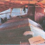
Bentley Construction carefully removed the existing terra-cotta roof tiles and stored them for reuse. Since the building was almost sixty years old, there was a considerable amount of tar stuck to the roof boards from constant contact with roofing felt. Removing the tar was the next task that construction site superintendent Kevin Higgs had to address. The tar instantly loaded sandpaper, and he could not use solvents because of the potential danger to the plaster ceilings just below the sheathing boards. Higgs finally elected to use wire wheels and/or wire cups mounted on hand held grinders to wear the tar away—a very slow process.
As they finished cleaning each section of sheathing, the Bentley crew members drilled the necessary oversized holes through the sheathing into the joists and potted the large wood screws in an annulus of epoxy. Because hundreds of oversized holes needed filling, we suggested the PRO-SET Epoxy Adhesive for this phase of the operation to save time. The pre-thickened components come packaged in two cartridges that resemble caulking cartridges. A special two-plunger caulking gun forces the resin and hardener into a static mixing tube where they are thoroughly blended. The construction crew injected the adhesive into the holes and positioned the screws in the uncured adhesive so the tops of the fasteners were flush with the top of the sheathing.
The construction manager chose Palmer Johnson, Inc., a manufacturer of large custom yachts, to apply the membrane. Their laminating crew has had extensive experience working with fiberglass and its quality is first rate.
Installing fiberglass and carbon fiber membrane in 13 layers is not a simple matter. Each seam in the cloth had to overlap the previous seam by a couple of inches. Creating the required cloth layout diagram was mentally challenging, especially where the cloth wrapped around a hip and valley. Pre-cutting the fabric in those areas also required a good deal of time to get it right.
The Palmer Johnson crew pre-cut the fabric into lengths just a little longer than necessary and stacked them in order of application. They used an impregnator to wet out the cloth. This machine feeds the cloth through a puddle of epoxy and then wrings out the excess on two adjustable steel rollers—not unlike the old wringer washing machines. The laminating crew set the roller gap to apply enough epoxy to the cloth to ensure thorough contact between layers of cloth in the laminate stack. They placed the wet cloth in position and rolled each layer with serrated metal rollers to remove large air pockets and wrinkles. They applied each layer of cloth according to the layout diagram, staggering the individual layers so the next stack would nest into the previous stack. When the crew finished each day’s work, they covered the fresh laminate with release fabric. The next day, removal of the release fabric was the only preparation needed to prepare the cured surface for further lamination. The fabric’s imprint provided the necessary texture for good adhesion of the next stack.
Several weeks later, when the entire laminating project was complete, the roof was post cured. This means the entire roof was “baked” for 24 hours. Kevin Higgs used a temporary furnace to heat the entire roof to 110°F. He covered the roof with insulating blankets and pumped the heat from the furnace under them. The temperature of the membrane rose to 110°F, remained there for 24 hours, and then gradually cooled down to room temperature. This completed the structural repair portion of the project. All that remained was to reinstall the terra-cotta roof tiles and metal flashing.
Silman Associate’s choice of epoxy for repairing Wingspread underscores the growing acceptance of these products outside of the marine field. The success of this massive undertaking is an excellent demonstration of epoxy’s viability in major structural applications.