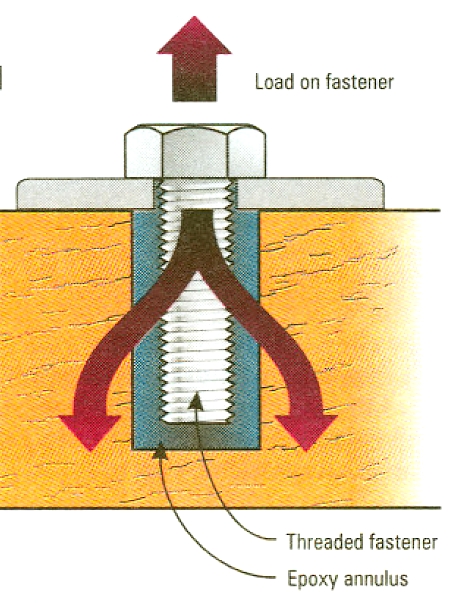
General considerations for epoxy bonded fasteners in wood
By Robert Monroe
With epoxy bonded fasteners, the idea is to balance the three parts, (fastener, epoxy and wood/hole) to obtain optimum performance. The key information needed is the tensile strength of the fastener, the shear strength of the epoxy and the withdrawal resistance of the wood or backing block.
The fastener dimensions and tensile strength should be available from various handbooks. We use a conservative shear strength of 800 psi for the 105/206/404 epoxy mix. The wood performance values are available in timber handbooks and vary by grain direction (i.e. is the fastener loaded parallel-or perpendicular-to-the-grain of the wood). Typically, one or more of the above factors are fixed and the others must be adjusted to fit a pre-existing condition.
Epoxy performance
We recommend 404 High-Density filler as the most cost-effective and easiest-to-use filler for hardware/stud bonding. Even small amounts of 404 help in reducing creep in the epoxy. We recommend a moderately loose slurry, the epoxy should be thick enough to stay in a horizontal hole but not overfilled. Too high a loading of 404 can result in possible air entrapment. Chopped glass fiber or carbon fiber can be added to the mix to increase the load carrying capability, but the additional cost and application difficulty are usually not worth it.
As mentioned above, we typically use 800 psi as the ultimate shear stress for the filled epoxy mix. This is a conservative value based on long term fatigue data. At this stress level, the epoxy is the limiting component. The interface between the fastener threads and the epoxy is the typical failure initiation point in fatigue. This is good. The fatigue failure mechanism for epoxy — cracking and gradual destruction of the matrix — gives some warning. A failure at the wood/epoxy interface or the loss of the bolt head is usually catastrophic.
Side-grain withdrawal from wood
The U.S. Forest Products Laboratory uses a formula to estimate the ultimate withdrawal load for a drift bolt or pin from the side grain of seasoned wood: p=6,600G2DL
- p = ultimate withdrawal load in pounds
G = specific gravity of wood @12% moisture content
D = diameter of hole (inches)
L = length of hole (inches)
This formula gives a good estimation of the wood’s resistance to withdrawal of the epoxy plug and can be used to determine the size of hole. The actual performance may be higher than the value derived above, but we recommend using the conservative value for estimation.
Wood screws — Tests done here on side-grain withdrawal of wood screws show a 100% increase in the holding power of a fastener imbedded in a 105/205/404 mix over the same fastener dry hole.
Endgrain withdrawal from wood
We look at the shear parallel-to-grain (maximum shearing strength) of the wood species to determine the performance of a fastener bonded parallel to grain. Selected values are given below. A timber engineering book should have additional values tabulated.
| Wood species | Shear Parallel-to-Grain | |
| Khaya | 1,500 psi | |
| Teak | 1,480 psi | |
| Luan | 1,200 psi | |
| Fir | 1,130 psi | |
| Ash | 1,500 psi | |
| Oak | 1,500 psi |
In a bonded fastener application, there is a cross-grain load in addition to the parallel-to-grain loads. The cross-grain tension will be greatest at the ends of the hole where the load is transferred from the fastener through the epoxy and out into the wood. This cross-grain tension necessitates the use of a plywood or FRP end-cap to prevent splitting of the parent block.
Hole size
For most applications where the shear strength of the wood is greater than 800 psi, we recommend a hole sized 0.25″ larger in diameter than the major diameter of the bolt. This gives an 0.125″ epoxy annulus around the bolt. We vary the length of the bolt and depth of the hole to balance the breaking strength of the bolt versus the withdrawal resistance of the epoxy plug. The 800 psi epoxy shear strength is the limiting value.
Example: A 3/8″ diameter 18-8 stainless-steel bolt with an UTS of 85,000 psi and an effective cross-sectional working area of 0.0775 square inches has a breaking strength of 6,587 lb. The hole depth should be the breaking strength (6,600 lb.) divided by the epoxy shear strength (800 psi), divided by the circumference of the hole (0.625″ x 3.1416 = 1.9635″) to equal 4.20″. In actual practice, we used a 5/8″ inch diameter hole with a depth of 4.5″ for a 3/8″ diameter bolt with 4.25″ of bonded length.
The above calculations need to be modified when you are limited in the depth of the hole allowed or when a short or oversized bolt is specified in the hardware installation. You do not want to cut away large portions of a keel or floor by using a grossly oversized hole. Likewise, you may be limited in a deck application by blocking location or overhead space limitations. In such cases, it is best to use the 0.25″ larger diameter, epoxy-filled hole to assist in stabilizing and securing the keel bolt, but use floors or metal pads to distribute the load.


