More on Laminating Wooden Beams
Spring 1999

GET STARTED
FREE PRINT & DIGITAL EDITIONS
Spring 1999
By Captain James R. Watson
When I was a kid, my older brother had a slingshot that was fashioned from a tree crotch. The wood fibers neatly followed the desired shape and nicely addressed the forces when operated. Centuries ago, many large ship components — knees, hooks, and floors were selected from forks, crotches and crooks of trees for much the same reasons. One-piece wooden parts were very reliable and the naturally grown beams and frames were key components of ship construction. As the availability of large naturally shaped timber diminished, large curved components were made of stacked and mechanically fastened smaller pieces of wood. Laminated wood structures weren’t possible until the relatively recent development of strong adhesives.
It is somewhat misleading to say that laminated wood superior in strength to solid wood. Wood fiber is wood fiber. What jeopardizes strength and reliability of a one-piece beam are its inherent defects. Strength and stiffness would be predictable and reliable if flaws such as knots, grain runout, grain dive and pitch pockets could all be detected and evaluated. To compensate for the possibility of hidden weakness designers are inclined to over-engineer by using heavier solid timbers. These days, the use of solid timber is limited to components that are mostly short and straight.
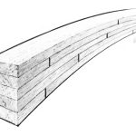
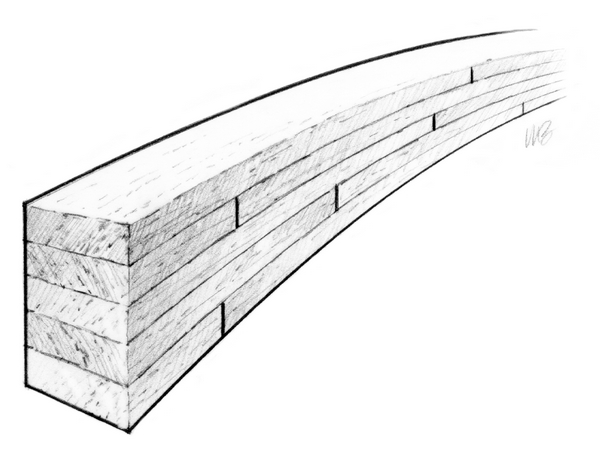
The reality of flaws in solid wooden components underscores the advantages of laminating wooden parts. With laminating, you can assemble the pieces, or plies, of a laminate stack to build a part to a specific shape (almost as if it grew to that shape) — orienting wood grain to address predicted stresses, minimizing waste, and reducing and dispersing flaws.
Joints can have the same effect as flaws in wood structures. The number of joints are often dictated by availability of good lengths of flawless timber. In solid wood components scarf joints are employed to join shorter timber end to end in an effort to maintain strength across the joint. Simpler joining methods such as butt joints require much less labor, but are much weaker and are stress concentrations. Where butt joints may be out of the question for solid timber construction, laminating allows you to use butt joints, because each joint has less effect on the overall strength of the part and joints, like flaws, can be evenly distributed throughout the part.
The load on beams and frames is generally unidirectional. The wood grain in both solid and laminated beams generally runs in one direction, parallel to the long axis of the beam. For structural components that do not carry a simple unidirectional load, laminating offers the opportunity to adjust the grain to the load direction. Although wood is much stronger along the direction of the grain, laminated wood can be made stronger across the grain by incorporating plies in directions other than the primary grain direction. By orienting every other layer 90°, plywood panels, for example, become stiff in two directions. While a strip of plywood would make a pretty poor beam, skewing laminations 5° to 10° from the long axis of the piece will improve cross-grain strength, but the piece would still be strong in the primary load direction. One advantage of skewing fibers at an angle is that it orients fibers more gradually throughout a bend, exerting less stress and allowing greater ply thickness.
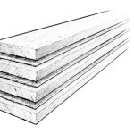
Choose the wood for a particular structure or part based on strength, stiffness, weight, cost, availability, the builder’s abilities, bondability and workability. All materials have a maximum bending radius — before compression or tension damage begins. If the wooden ply will not negotiate the bend at a given thickness, then thinner material is required. Thin materials negotiate a bend more easily than thick ones and more laminations of thinner material better resist springback.
Also, when wood is sliced into thin plies, trapped stresses are relieved; when bonded back together the resulting laminate is more dimensionally stable — able to resist the swelling, shrinking or warping that a thick one-piece component may produce (especially when exposed to fluctuations in humidity.) A good example of the value of thin laminations is in a guitar neck where stability translates into more consistent tuning.
As with any technique, there are variations of basic methods that can improve wooden laminates:
To taper the laminates individually, first determine the amount of taper in each ply, from the thickest cross section to the thinnest. Then make a master that is the reverse of each ply. The master will support each ply as it is passed through a thickness planer. The planer will remove the most material from the ply over the thickest part of the master. All of the plies will be tapered identically and when laminated only the sides of the component need finishing.
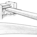
Layout the desired curved shape of the part onto any flat work surface (a floor or a bench). Attach triangular knees or cleats along one side of the line of the curve. To keep the laminate from bonding to the work surface place a plastic sheet under the cleats. Attach an additional cleat opposite each cleat on the line. Leave enough space between opposing cleats to easily fit the epoxy coated plies. When all of the plies are positioned, insert wedges between second row of cleats and the ply stack. Tap the wedges in to clamp the laminate firmly and evenly against the first row of cleats.
Ideally, enough epoxy is applied to all mating surfaces so that a small amount squeezes out as clamping pressure is applied. Even contact is all that is required between mating surfaces — too much clamping pressure only pre-stresses joints and forces adhesive from the joint, which could result in a glue starved joint.
Be careful that the plastic does not find its way between plies when drawing them together. Cover the cleats and clamps with plastic to keep them clean. Spraying mold-release on clamps is also a good idea.
Laminated parts can offer many advantages to the builder. As with most projects, planning ahead is the key to success. A little innovation also goes a long way.