Building a wood/epoxy Sharpie, Phase I
Spring 2000

GET STARTED
FREE PRINT & DIGITAL EDITIONS
Spring 2000
By Captain James R. Watson
When I was building my first boat, my dad used to drive me nuts as he sat in his rocking chair considering “how to proceed.” I wanted to see the chips fly. Now, after many of my own projects, I realize the wisdom of studying the sequence of events from the beginning of a building project to the end. Building projects are a lot like a child’s dot-to-dot puzzle. There is often a best order to the steps that can save time and money, improve quality, and most effectively utilize your shop space. So often I have foolishly rushed to build the easy and rewarding components only to have them take valuable room and leave me late in the project to struggle with time consuming keels and rudders.
With my most recent project of building a 29′ sharpie with wood and epoxy, I’ve tried to think carefully about my order of building. I built the frames and daggerboard and case first because they take little room, not the main shop space (in my case, half a garage that requires winter heating). I built the daggerboard and its ballast component before the daggerboard case because then the case can be built to fit the board. I also finished interior surfaces before closing them off, installed components while there was still easy access, precoated and sanded parts on a bench rather than waiting until they were in place.
With any project, it helps to think carefully at the outset about the entire building process so that you can be more efficient. Make every step a clear step forward (without two steps back) to the next dot in project completion. I’ll share some tips with you, as well as a few of the nonconventional approaches I am taking in building the sharpie.
Select the design
Ever since I was a kid, I have wanted to build a sharpie. These relatively narrow, flat-bottomed skiffs evolved in the 19th century. They’re pretty boats and have often been praised as offering the most performance for the least investment. I liked their virtues of shoal draft and good sailing characteristics with a speed potential. Sharpies can make good pocket cruisers that can be trailered easily and open up many new cruising grounds. They’re also relatively simple to build. The first step in any successful boatbuilding project is selecting a design. As I’ve written before, too many folks want to be designers, but after all the hard work end up with a fundamental design error that dooms the entire effort. Sharpies have evolved over 150 years and the designs of Howard I. Chapelle and others are well proven. I wasn’t about to design my own. I bought plans for several similar designs before selecting this Howard I. Chapelle’s DANDY, a development of Commodore Monroe’s popular EGRET. The boat is 29′ length overall, with a 7’6″ beam and an 8″ draft (Figure 1).
I planned several variations, however, the most important being a ballasted daggerboard, molded composite chines, and a high performance rig.
Choose quality wood
For many applications, several choices of wood are possible. Be sure you understand the physical properties of the species you select. You will also need to consider cost and availability. Here are some of my thoughts on the choices for the sharpie project.
Stringers
I chose Douglas fir for the stringers (including chines, clamps, keelsons, frame and bulkhead perimeters, etc.) because of its cost and availability in the Midwest. I bought 20′ clear vertical grain (VG) Douglas fir for about $3.70 a board foot. Another good choice for stringers is Sitka spruce. It is lighter than fir but the cost is about double. (Prices will vary, but the comparative prices between species stay about the same). Cedar is too soft for these components. Stems, daggerboard, daggerboard case ends, rudder
I selected Honduras mahogany for stems, false stems, daggerboard, daggerboard case ends and rudder. Mahogany’s attributes are strength, dimensional stability, and durability. Bulkheads, daggerboard case, and planking
I chose marine-grade Okoume plywood for all bulkheads, the daggerboard case, and planking. Where 1/4″ thickness is used, I prefer 5 ply over 3 ply because it is stiffer. I recently saw a large catamaran built with mahogany plywood and WEST SYSTEM® epoxy that has spent her life in the tropics and there was no checking and no moisture damage, a credit to the builder and the construction materials. Another option would be marine grade fir plywood. I’ve built several boats of this material which are now 25 years old and still going strong. However, marine grade fir plywood has a tendency to check which even covering with glass may not contain.
Many wonder if AC grade plywood will work for boat building. It will, but the voids and knots will be a source of problems and should be filled with epoxy. I’ve found AC grade plywood ends up costing so much more in time and epoxy to repair to bring it up to speed that it is not a good choice.
Fabricate stock before storing When I unloaded my lumber, I already knew member sizes and shapes. So I ripped all stringers to width and shape (chine stringers are trapezoids) before storing. All the longer pieces would require was scarfing to length later. Then I carefully stacked the lumber in order of use, placing 3/4″ x 3/4″ sticks spaced at about 6′ intervals between layers. Pre-finish whenever possible.
Whenever possible, I prefinish parts and surfaces. It is much easier, neater and quicker to sand and coat parts on a bench or when there is good access. Crawling around inside the hull with a sander and roller is difficult and time consuming, and the quality suffers. Typically, because the interior will be finished clear, I apply one coat of WEST SYSTEM 105/207, sand it, and give it another coat. I don’t apply the second coat where I know there will be a joint (temporary fasteners used during dry run fitting and trimming help identify the areas). I can avoid having to sand there before applying epoxy for bonding.
Building frames
I build my frames on a mold table on which I laid out the body plan when lofting, taking care to mark the waterline and centerline. I use heavy, clear plastic on the table to keep the adhesive off and to let me see my lines. I produce all stringer notches and limber holes at this stage. Then I fasten components together in a dry run, using drywall screws.
Use removable fasteners
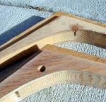
I then glue the components together on the loft table, using the screws for clamping pressure after coating them with Stoner™ thermoset mold release E497 for easy removal. I check the assembly with the lines on the table to make sure nothing has moved. After the epoxy has cured, I remove the drywall screws and counterbore all holes with a countersink. Then I bond in plugs made on the drill press with a plug cutter, using the same species of wood. When the epoxy has cured, I trim the plugs with a flush-cutting saw (Figure 2). Why not use permanent fasteners? Exposed endgrain that fastener holes expose is a common source of moisture related problems. Moisture can travel down the fastener via condensation. With everything bonded rigidly, nonferrous fasteners are redundant. They are also expensive (for example, #8 x 1″ are 50 cents each). With plugged holes, all is permanently sealed. However, some high stress situations may require fasteners. These are set in wet epoxy while being installed to improve cross grain strength.
Radius the edges
All edges (except where planking and stringers join) are rounded with a router. I use a 3/8″ radius double flute bit. Corners are vulnerable to damage and are sharp when you bump them. Radius edges coat more easily and leave an uninterrupted coating which accelerated weather testing in the laboratory as well as my firsthand experience with many boats have shown to hold up much better.
Coat and sand
I then coated all surfaces with two coats of WEST SYSTEM 105 Resin/207 Special Coating Hardener. I decided that on most of the interior, this would be my finish. No varnish. Most of the boat interior will not see the light of day and those areas that will see only indirect light. Two even thin coats with no runs or sags is clear and glossy and will hold up great in this application. I also lightly sand any surfaces that will be varnished (with either a satin or a water-based satin varnish), so it won’t have to be done later. This includes the visible interior of the cabin.
Making the daggerboard
One of my design modifications was the centerboard. Sharpies usually carry a drop type of board that is hinged on an axle. Some sharpies have two (tandem) boards, some leeboards. I modified the traditional designs to use a ballasted daggerboard. I chose a daggerboard because the clean exit from the hull and the aspect ratio make it more efficient. Its small slot size reduces lost hull displacement. A daggerboard also takes up less room in the cabin.
I chose a NACA 0010 foil section for the board. I built the daggerboard and ballast component before the case so I could build the case to fit the board. It’s hard to modify a NACA foil section, but you can easily modify the case for a precise fit.
Basically, I followed the procedures outlined in the Gougeon Publication 000-448 How to Build Centerboards and Rudders. However, I modified this method by ripping the strips to specific widths dictated by the template. This saved material and minimized machining. I also sawed a 1/2″ deep slot in the ends of each strip into which thin 1/8″ plywood would fit snugly. Thus, I was able to align the laminate during the gluing operation (Figure 3).
Adding ballast
The daggerboard has lead ballast on the end. I wanted to be able to hoist the board completely, so I needed the lead to be the same foil shape as the board (rather than a bulb shape). The ballast weighs 200 pounds.
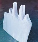
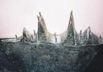
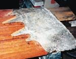
I used the “lost foam” process to produce the ballast. I first needed a foam plug the same shape as the board. I glued foil section plywood templates to each end of an oversized block of blue insulation foam. I then wrapped thin piano wire around two wooden dowels and connected the wire with alligator clips to my truck battery. I pulled the hot wire taut and dragged it across the templates, cutting the foam to the exact foil shape in about 30 seconds. I added some peaks to the top of the ballast to key into the board (Figure 4). Then I placed the foam in an oversized hole dug in the yard and filled around the foam with Portland cement, allowing it to cure for a week. I had some buddies come over to melt the lead and do the pour. We built a wood fire, added charcoal, and supercharged it with my shop vac. We melted miscellaneous lead scraps and wheel weights in an iron pot cum crucible. (I was also using bread pans to mold 25 ingots at 35 pounds each for internal ballast.) The foam plug vaporized as we ladled the liquid lead (over 600°F) into the mold. It bubbled, hissed and gurgled for a few minutes, and half an hour later we were digging it out of the ground. Light taps with hammers cracked off the Portland cement, revealing the accurate casting.
Using hardware bonding techniques, I drilled holes in top of the lead ballast, and then bonded in 3/8″ stainless steel threaded rod (Figure 5). We know that you can get about 1,000 lb. per inch of bury into wood as well as lead, so my 12 threaded rods with 2 to 3 inches of bury was overkill. I prefit the ballast to the board (Figure 6), before bonding the two with epoxy thickened with 406 Colloidal Silica Filler.
Making the daggerboard case
Once the daggerboard was completed, I built the daggerboard case wide enough to allow for clearance. My unique approach to constructing the case allowed me to complete all treatment to the interior before closing the case. Of course, once the case is closed, access is severely limited. I bonded the Okoume daggerboard case ends to one plywood side producing a 1″ radius interior fillet. For abrasion resistance, I then applied a layer of 6 oz fiberglass. I also glassed the remaining side that was not yet attached. Next, I applied a thick 1/32″ coat of 425 Copper Additive. I used copper additive for several reasons. First, it is very hard and takes abrasion well—abrasion from potential rubbing from the daggerboard over the years. Also, the copper additive has some antifouling potential so it may aid in preventing marine growth. From experience and testing, we know that it will at least make the surface easier to clean. Once all of the interior surfaces were cured and sanded smooth, I bonded the adjoining side. Then, as with the frames, I prefinished the daggerboard case exterior with WEST SYSTEM 105/207.
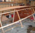
Assembling strongback, frames and stringers
At this point, I decided I was ready to commit the shop to assembling the whole boat. Jig construction and frame setup were straightforward. The strongback was a simple 2″ x 4″ ladderlike structure that assured accurate frame placement. I installed the 8″ wide scarfed-to-length keelson first. Then I could use it as a sort of long bench on which to scarf the 6 other stringers (2 clamps and 4 chines) to length.
Installing the daggerboard case
I installed the daggerboard case before any planking or stringers. That way, I didn’t have to duck or negotiate around them. I cut the keelson with a slot that duplicates the daggerboard foil shape. A method for aligning the case that works well is to fasten the case to the keelson with lag screws at each end of the case. The holes through the keelson are made oversize and oblong athwartship. This allows precise alignment and marking in the dry run and when bonding permanently.
Building and prefinishing other parts
Next, I fit the scarfed-to-length chine stringers only. Then, while I still had good access, I produced the bunk and cockpit sole. These horizontal elements are otherwise difficult to fit after the installation of side panels. After fitting, I coated these plywood parts with epoxy and set them aside. Then I installed the chine stringers (Figure 7).
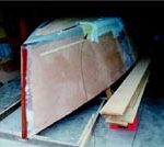
Applying the bottom
The flat bottom of the sharpie is easy to work on and with a subtle rocker is easily bent into position despite the 3/4″ panel thickness. I fit and scarfed together all panels at an 8:1 bevel. I glued them down in one operation, cleaning off all excess adhesive prior to curing (Figure 7). (I will later modify the bottom to a slight 3/4″ arc with lead ballast slabs molded in amidships.) I again used drywall screws sprayed with release for temporary fasteners and then bunged the holes.
Installing the side planking
I never thought I’d put butt blocks in a boat after the poor results with a MICRO project where the butt block areas showed flat spots. This was probably due to the short wide shape of the boat so that the tight, fair curve was interrupted with the localized reinforcement of the flat butt block. On the other hand, some of my oldest projects with butt blocks, including the trimaran ATOM with its long subtle shapes, have looked just fine. (See Epoxyworks 7, Spring 1996 for some comparisons of butt blocks and scarfs.)
So why butt blocks on this boat? The sharpie hull resembles the long shapes of the trimaran more than the short beamy shape with which I’ve had difficulties. I’m building this boat by myself. A complete panel all scarfed together would weigh on the order of 90 pounds. Even if it weighed half that, at 3′ by 30′ it is unwieldy. With wet adhesive on all the contact points, accurate placement would be futile. An alternative would be to scarf in place, but it would be very difficult to align scarfs. Thus, the butt block.
First, I fit all the planking panels, overlapping the adjoining edge slightly. Then I marked this so the edges matched perfectly. At the same time, I marked all stringers and frames. I also prefit all butt blocks. They are plywood, 30% thicker than the planking, placed between the stringers with the face grain running parallel to the planking. After fitting, I removed all panels and coated them with WEST SYSTEM 105/207, sanded and applied a second coat. I didn’t coat the areas where the stringers and frames joined so they would not require sanding before bonding. After one panel was joined to the hull, I screwed and glued the butt block down. The second panel was then simply put in place and similarly glued and screwed to the butt block. Again, I used drywall screws for clamping.
One of the negative aspects of the butt block is the exposed endgrain of the butting panels. To solve this, I used a disc grinder to dish out a generous scoop of material centered over the butt, about 8 times the depth in each direction. Then I bonded in multiple layers of successively smaller strips of biaxial fiberglass to fill the joint and faired it smooth.
Building composite chine reinforcement
My approach to building and installing the chines deviates from traditional plywood construction. Not only did I reinforce the chine with composites, but I also premolded them. The chine is the corner that is formed where the sides and bottom of a boat join. Large buildups of wooden materials for reinforcement at corners (especially chines) are susceptible to dimensional changes that lead to cracking and then moisture ingress. Replacing the wooden chine buildup with a composite reinforcement resolves this situation. Composite chine construction methods have been used successfully for many years. I first used them on a plywood Searunner™ trimaran. Now 25 years old, its chines are perfect, a testimony to the soundness of the concept.
In the sharpie, two trapezoidal shaped stringers run along the chine, one on the side and one on bottom, about 4″ from the planking joint. They form a trough along the interior of the joint into which biaxial fiberglass cloth reinforcement can be laminated. The chine exterior is rounded and covered with several layers of 16 oz fiberglass cloth. As well as eliminating moisture problems, this rounded chine offers hydrodynamic benefits by reducing the drag-causing eddies created around sharp corners as a boat sails.
With the boat upside-down, laminating multiple layers of fiberglass with epoxy overhead poses obvious problems. One option is to roll the hull over, but this is no easy task with an awkward 700 lb hull that may not be as rigid as desired and can stress the glue joints or other components. Instead, I decided to produce the inner chine reinforcement in sections on a mold and install the cured composite parts overhead.
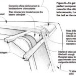
Molding the composite parts
Initially, I had planned to make a mold for the parts using PVC pipe with tangent flats made of blue insulation foam taped in position at the angle of the side and bottom chine joint. However, to get the perfect compound curve, I decided to use the hull as the mold. First, I shaped the radius on the chine exterior, filling and fairing where the sides and bottom joined. Then I marked the stringer and frame locations and covered the area with 6-mil polyethylene to provide a release medium. I had to make the composite reinforcements in 5 sections so that I could install them under the frames (Figure 8). Once they were in place in the boat, I would join them into one continuous piece.
A chine can be subjected to more force than the hull panels, so adequate buildup of the chine reinforcement is important. My laminate was built up from 7 layers of 8″ wide, 15 oz. biaxial/mat fiberglass tape to about 1/4″ thickness. I used one layer at the extreme edge of the tangent and staggered the tape to produce 7 layers at the apex. I tapered the ends of each section. After they are fit in the boat, the sections will be joined together by adding layers of biaxial tape and epoxy. I released the boat from the strongback and raised it so I could get underneath and install the composite sections at a comfortable working height. I installed the sections between each of the frames and the chine stringers in a layer of epoxy thickened with 406 Filler. After all of the composite sections were installed, I reinforced the exterior of the chine with 3 layers of 15 oz. biaxial tape.
Fiberglassing the bottom
The bottom of the hull gets one layer of 6 oz fiberglass cloth for abrasion resistance. To strike the boottop and waterline, I followed the method described by Larry Pardey in Details of Classic Boat Construction. While he doesn’t like epoxy much, I could adapt his procedure to trim the top edge of the fiberglass for my “cut in line”. I applied the cloth down over the chines past the designed waterline about 4″ to 6″ and cut the fiberglass straight and clean with a circular, razor-bladed fabric cutter. The edge that now exists is an excellent “cut” edge for painting.
To apply the fiberglass, I used the dry method described in our manuals. I added 503 Gray Pigment to the last of the coats to fill the weave. I’ve had good success with this approach and the pigmented bottom gives the craft look of continuity.
I glassed the topsides with a layer of 4 oz. fiberglass cloth to the cut line and pigmented it with 501 White Pigment to serve as a sort of primer. The boat was finally ready to leave the shop. Now I can dedicate that space to building the freestanding composite spars.
Be sure to read my follow up article, Building a Wood/Epoxy Sharpie, Phase II.