Building Composite Tubes
Spring 2008

GET STARTED
FREE PRINT & DIGITAL EDITIONS
Spring 2008
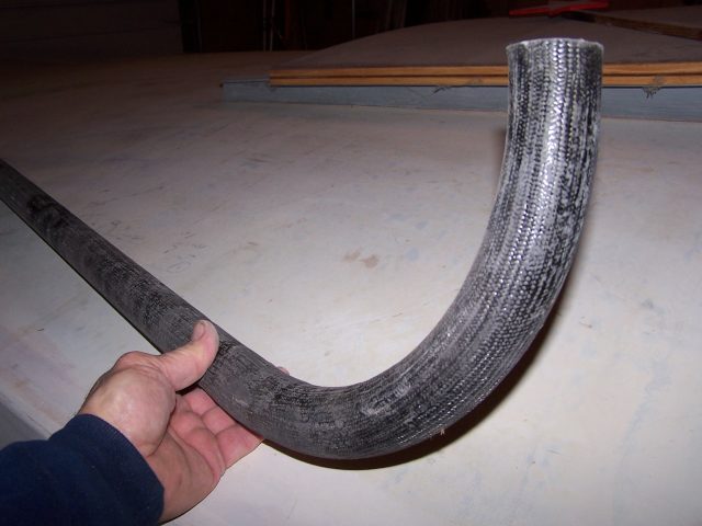
Above: A tapered composite tube section joined to a curved section.
Composite tubes are used on boats for hardtops, T-tops, Biminis, dodgers, bows, bow and stern pulpits, rails, canoe, and kayak paddle shafts, boat hooks, and so on. Composite tubes built with epoxy and reinforcing fibers offer advantages over metal in terms of lightweight, custom shapes and sizes, and corrosion resistance.
Composite tubes can be faired and painted to produce a seamless appearance to match the boat, or left to show the carbon fiber. I’ve been experimenting with approaches to building a variety of composite tubes. Following are some things I’ve tried (some that worked and some that did not) that you may find of value if you want to produce composite tubes yourself.
For all of these composite tube projects, I chose WEST SYSTEM 105 Resin and 207 Special Clear Hardener. The hardener choice was driven primarily by the desire for plenty of working time, fast wet out of the fiber reinforcement (as I was often unsure how long it would take to accomplish what I had in mind), and the option of a clear finish.
The real challenge in building composite tubes is in creating the mold or mandrel (the core around which material can be cast, molded, or otherwise shaped) and releasing the composite successfully from the mold. Fiberglass over a metal tube is a typical approach; however, I also experimented with using foam pipe insulation as a molding surface. To form the composite tube, braid is slipped over the mandrel, wet out with epoxy, and then reinforced with additional fiber/ epoxy laminates to the desired thickness. The composite tube is then released from the mandrel, and the sections are joined together if needed.
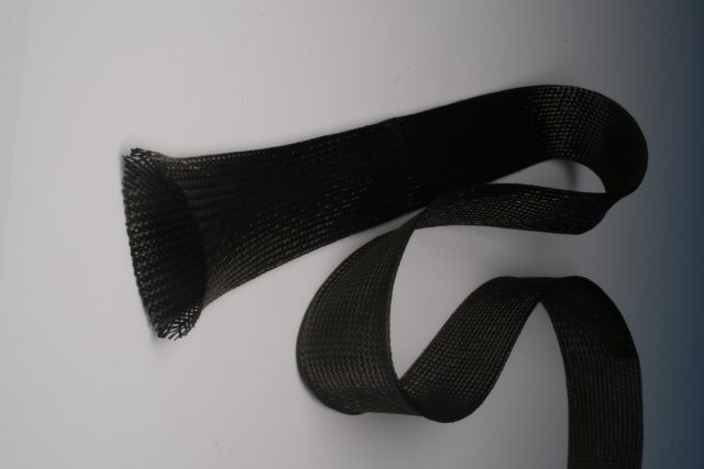
Braided fibers are a good choice for composite tubes. Braids are available in fiberglass, aramid, carbon fiber, and other materials. A sleeve or tube of braided material behaves like a Chinese finger trap (Figure 1). Because the fibers are woven together at 45°, you can simply pull the braid to lengthen it. This also reduces the fiber orientation to about 35°. The material to lengthen is “stolen” from that formerly used to keep it wide. Total surface area remains constant, so the more you lengthen it, the more the diameter shrinks (i.e., tightens). The reverse effect is that if the ends are pushed, the diameter increases with a likewise increase in the fiber orientation to about 55°. This, of course, is how the finger trap is removed; because the diameter is now larger, it slides off your fingers. This expansion and compression of the braided tubes can be utilized in the construction process.
In these projects, I used carbon fiber braids. Specifically, I chose 3K (3,000 fibers per bundle) .06 oz/ft carbon fiber braid purchased from CST, The Composites Store, and A & P Technologies. These companies also carry braids in tape form, rather than sleeves. Tapes behave like biaxial but are much more controllable as the braid yields a straight edge that does not unravel. Tapes go around a corner nicely and can be manipulated like the sleeves by pulling or pushing to alter fiber angle.
My simplest and most successful approach to creating molds for composite tubes is to laminate a thin layer of fiberglass over a smooth metal pipe or tube (could be aluminum, chrome, steel, etc.) that serves as a mandrel. Wax the tube. It must be very smooth to facilitate removal. Apply a thin layer of fiberglass with epoxy. After this thin layer has cured, cut the laminate along the tube’s length with a utility knife and pop it loose but still on the mandrel. Rotate it a little to make sure it is free.
Then, continue with the desired laminate schedule. The fiberglass has already been released, so the composite tube will slide easily off the mandrel.
A second approach uses rope and foam pipe insulation (with a self-sealing slit) that looks like a doughnut in section. The foam has a slippery surface to which the epoxy does not bond very well, facilitating removal when used as a molding surface.
I strung a length of low stretch rope (about 25% greater than the desired tube length) between two points tensioned with tackle. Initially, I left the rope unattached on one end. Alongside the rope, I also strung the same length of 50 lb monofilament fishing line. I covered the rope and monofilament with 1¼” OD slit foam used for pipe insulation. It comes in 4′ lengths and is sized for about a 5/8″ diameter pipe.
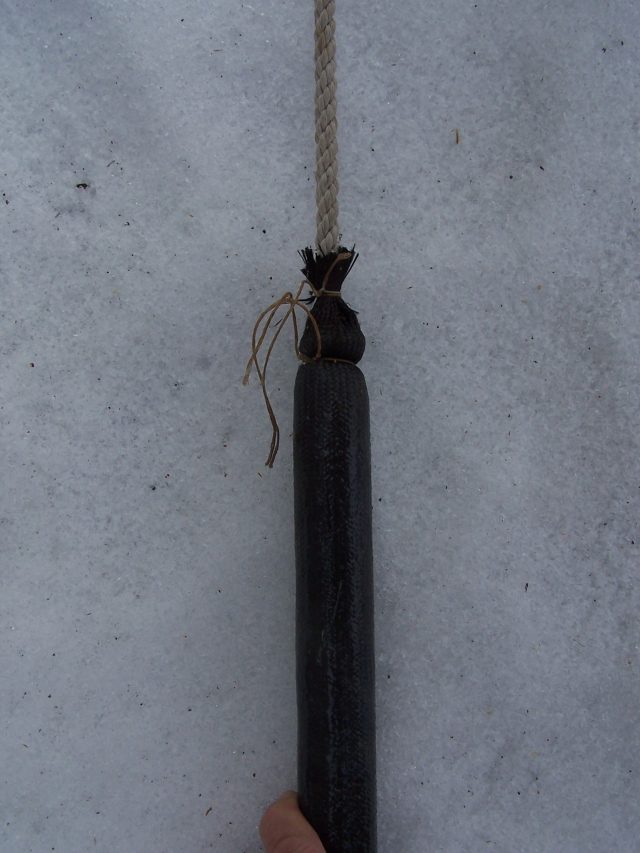
I fed one layer of braided sleeve onto the foam. I followed this with a second layer. However, the second layer was gathered at the “long end” where the 25% extra rope was situated. Then I tensioned the rope to reduce any curve or sag and worked the braid toward the ends of the tube to tighten it against the foam. Next, I wetted out the braid with WEST SYSTEM® 105/207. I placed layers of 703 Unidirectional Carbon Tape over the braid and wet it out with more epoxy. In this way, I could step-taper these layers to achieve a buildup of thickness in the center with less on the ends. Once I had achieved the schedule I wanted, I slid the outer braid up over the unidirectional laminations using waxed twine so I could pull and work one end of the braid toward the opposing end and tie it off (Figure 2). Once the braid was smooth and secure, I wet it out and let the tube cure overnight.
After everything had cured and I removed rope, I used the 50-lb monofilament to cut the foam into segments so it could be removed. The monofilament is like dental floss. Using a sawing motion it cuts right thru the water pipe foam insulation almost as if it were butter. I was eventually able to get the foam out, but not without some difficulty as it was stuck to the inner carbon braid. This approach works on sections up to 10′, but may not for longer lengths. Considering how little weight the foam represents, it may not be worth the effort to remove the foam.
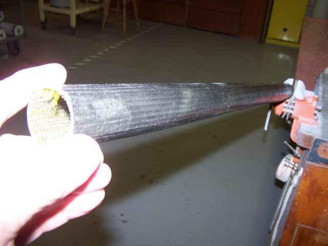
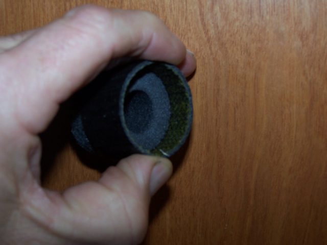
Another approach I tried was to cover foam pipe insulation with PET plastic braid, commonly used to cover cables or electrical wiring, with the intent to force the foam to become more round. Tests where I tried to bond to the PET resulted in what I wanted—the epoxy didn’t bond to it, which seemed to allow easier removal of the foam, although the PET remained inside the composite tube (Figure 3).
An approach I tried that didn’t work was to laminate over a fluorescent light tube. I liked the idea as the inside surface would be perfectly smooth. I applied mold release to the glass tube and laminated the carbon fiber braid and unidirectional fiber as described above. The plan was to break the bulb (they implode) and vacuum the particles out. However, I was disappointed when I broke the end and the bulb did not implode but stayed attached to the carbon fiber. Evidently, there was too much surface area to allow removal. So I have a carbon fiber tube that is glass-lined.
Based on this lesson, I tried a different approach. I bonded a light layer of fiberglass fabric over the florescent tube with mold release on the surface. When cured, the single layer of fiberglass is flexible enough that you can break the bulb and remove the broken glass. I then laminate enough fabric to the outside to yield the required stiffness. Now I have a composite tube that is perfectly smooth and round inside.
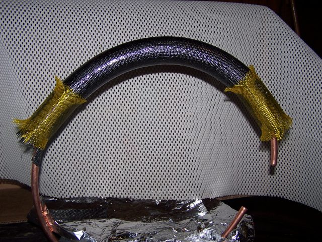
To make curved tubes, I bent ½” diameter copper tubing to about an 8″ constant radius. Then I placed pipe insulation foam over the copper tubing and proceeded with the laminating. When everything was cured, the copper tubing slid out. Again, I used monofilament to cut the foam to allow removal in pieces.
To make a tapered tube, I placed pipe insulation foam over a metal tube that was greater than the size the pipe insulation was intended for, which opened the slit. Then I attached eyebolts to each end of the tube and stretched two 50 lb monofilament lines. I aligned one end of each with the edge of the open slit of the pipe insulation and the other end on the foam away from the edge to form the desired taper. Using the line as a guide, I then cut along the lines and remove the long thin wedges of foam along the open slit. I placed the trimmed foam over a taut rope as described earlier. When I sealed the slit shut, I had a tapered molding surface to laminate over.
To create one continuous tube, sections—straight or curved—can be joined to other sections. I wanted matching diameters within a 1/16″ so I could easily blend the sections to become visually “joint-less.”
I’ve used two approaches for joining tubes and both involve fabricating a sleeve that fits in the ends of the tubes. The sleeve length should be about four times the diameter of the tubes you are joining—half of the sleeve length goes into each adjoining tube.
The first approach to creating a sleeve is to follow the procedure described above for laminating one layer of fiberglass over a polished metal tube and then cutting the laminate to free it. After that, add a couple more layers to get the outside diameter needed to match the inside diameter of the tubes to be joined.
The other approach I used was to laminate a sleeve over a thin wall (1/16″ or less) aluminum tube mold. The outside diameter of the aluminum tube represents the inside diameter of the tubes to be joined less the thickness of the sleeve. After sanding and polishing the aluminum tube, I wrapped it in fiberglass tape saturated with epoxy. Then I heated the aluminum and the laminate to accelerate the cure and also expand the aluminum.
After it all was cured, I placed the laminate in a snowbank (a freezer will work) to shrink the aluminum. A 70ºF temperature drop is usually sufficient to allow the cured laminate to slide off the aluminum tube. I sanded the sleeve to adjust the fit and then bonded it to the inside of the tubes to be joined with thickened epoxy.
Composite tubes offer lots of possibilities. I hope you find some of these approaches helpful.


