by Captain James R. Watson
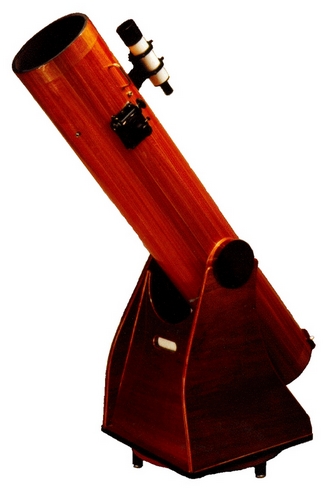
We have all looked to the night sky and been taken aback by the view. Telescopes are tools that allow us to get a closer, more detailed view. My dad used to call them “a ladder to the heavens.” There are a number of reasons why you might want to build your own telescope: Custom design, aesthetics and quality come to mind. There is always the element of satisfaction in creating your own. I chose to build this particular telescope to observe the heavens and reel in some astounding views. This project is not as difficult to construct as it sounds. The configuration and components are straightforward.
You won’t save money building a telescope like this one. You could buy a fine telescope similar to the one I’ve built, for the cost of the building materials and components. If you built the components yourself, you might save money. However, you’d have to grind your own mirror—a project in its own right and beyond the scope of this article. Building this instrument may give you enjoyment, and the completed telescope will give you, your family and friends a life time of viewing pleasure.
My goals for this project
I wanted to build a high quality, portable and aesthetically pleasing telescope. I didn’t want building it to consume too much time. I was willing to work at it part time for a few months, make some of the parts, buy others and assemble them all.
The main parts of a telescope are the optical components, for viewing, and the base, for holding the scope steady and allowing adjustments. I chose a Newtonian type of reflecting telescope, named for its inventor, English physicist Sir Isaac Newton.
The optical components; the primary mirror, secondary mirror and focusing mount are attached to the optical tube. Light enters the hollow, open-ended optical tube and is reflected off a large, curved primary mirror at the tube’s base up to a smaller flat secondary mirror near the front end of the tube. It’s reflected again out of the tube into the eyepiece in the focuser. The tube’s interior is baffled to reduce stray light.
The tube rests in a simple and efficient base, designed by the U.S. telescope builder John Dobson. The Dobsonian mount permits precise movement toward the objects you wish to view. Its drawback is that it doesn’t allow tracking for photography.
Because the scope is portable, the less it weighs, the better. I decided to make the optical tube out of cedar. The simple cylinder shape makes it perfect for strip-planked construction. And because it is encapsulated in epoxy, it is dimensionally stable and resists weathering, although I’d never leave it out in the rain. This kind of scope is relatively inexpensive and doesn’t call for exotic manufacturing steps, so a home-builder can make one.
Laying it out
I laid out the telescope, full-size, on a piece of plywood (boatbuilders call this lofting). For the optical component, I wanted the biggest aperture practical for a portable scope, to gather more light and allow me to view fainter objects in the night sky. I decided on an 8″ diameter, f6 primary mirror. This choice drove all of the telescope dimensions. I began with the primary mirror, and its 48″ focal length. The focuser and secondary mirror I had chosen, determined the distance from the face of the primary mirror to the center of the secondary mirror. I added a few extra inches and made the optical tube 56″ overall. The extra length helps reduce stray light and prevent dew on the secondary mirror. The added length does make the scope more cumbersome, but I feel it’s worth the tradeoff.
At the location of the secondary mirror, I drew a cross section of the tube. A mirror this size requires an optical tube with a 10″ inside diameter. I determined the number of wooden strips required to build the tube and the bevel angle for the strip edges. Adding the thickness of the strips to the inside diameter gave me the mold frame dimensions.
Building the optical tube mold
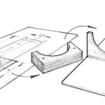
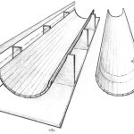
The mold in this project serves two functions. It is first used to build the optical tube halves, and later becomes part of the storage case. The optical tube is simply a hollow, open-ended cylinder. It would be built in two halves then glued together. I made three female mold stations of ¾”-thick plywood to support a half of the optical tube. The tube’s wall thickness is 3 8″ so the inside mold surface diameter is 10¾”. I made the stations identical by screwing them together and making all the cuts at the same time. I made the mold frames 2″ larger than the optical tube on the sides and bottom. Then I separated and glued the three stations to a piece of ¼”-thick plywood that would become the bottom of the storage case. I placed one in the middle (see illustration) and the others about 6″ from each end of the optical tube. To keep the form flat, I temporarily screwed it to my flat workbench. I used this form for many alignment steps and as the foundation for the telescope’s storage and transport cabinet.
Making the optical tube
To build the optical tube, I needed a dimensionally stable wood that would plane, sand and bond well. I chose western red cedar. Redwood would have been another good choice. Mahogany would have looked very nice but added some weight.
I ripped the strips from a flat sawn 2″ × 10″ × 6′ planks, so I ended up with quarter sawn strips 3 8″ thick × 15 8″ wide. The strips are 16″ longer than the finished telescope tube. I cut enough strips to allow for 20% reject after examining for grain flaws, and bought extra stock for the altitude bearing pads (discussed later). I selected my strips for the tube, numbered them and flipped every other strip end for end to limit dimensional change and counter the grain runout.
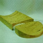
I beveled the strip edges to the angle I’d established by lofting. You can rip the strips at an angle on the table saw or shape them with a plane as I had done. An easy method is to attach a bevel guide block to the plane’s base. Building one half at a time, I dry-laid all of the strips for the first half into the mold frames. I trimmed the two end strips flush with the top of the mold frames, then numbered and removed the strips.
To prevent the strips from adhering to the mold frames, I covered the frames with polyethylene plastic. One by one, I coated the edges of the strips and laid them in order into the female mold frames. I used epoxy mixed with 407 Low-Density Filler so that it would sand at a similar rate to the wood.
I stapled wooden strips across the top of the mold frames, forcing the end strips down. The pressure forced the strips together and against the frames, like an upside-down arch. I was able to clamp all of the strips at the same time without putting holes through the strips. I made sure all of the strips were aligned, scraped off the excess and allowed the epoxy to cure.
Before removing the tube half from the mold, I bonded 6″-wide, 9 oz. glass tape 8″ from the ends on the inside of the tube to prevent cracks. The next day, I removed the tube from the mold and repeated the process to make the other half of the optical tube.
Baffling
Baffling is the texturing of the inside surface of the optical tube to ensure that the only light that reaches the eyepiece is the direct light from the object it’s focused on. To make the baffling, I bought fine sand (the kind used to create terrain on scale train sets). The grains are consistent in size and color. I coated inside the tube halves with epoxy, then sprinkled the sand onto it before it had gelled. After it cured, I spray painted the surface flat black. It was easy to accomplish this while the optical tube was still in halves.
The textured surface absorbs 90% more light than a smooth surface painted flat black. Its drawback is that it’s difficult to keep clean, and dust is light colored. It’s easy to wipe clean a smooth, flat black tube, whereas you must vacuum or periodically repaint a textured tube. This is time consuming, because you must remove the mirrors or mask them to protect them from paint.
Joining and finishing
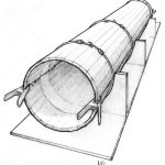
Next, I carefully aligned and joined the two halves. I held them together with three bungee cords that exerted moderate pressure around the tube. Spring clamps at the ends kept the joints aligned. When the epoxy cured, I used flat black paint to touch up the slight adhesive squeeze-out on the inside. Using the mold to support the tube, I lightly planed the faceted exterior round, then I sanded it with a flexible sanding block that conformed to the round shape. (Flexible sanding blocks are described in Epoxyworks 5.) I began with 40-grit sandpaper, then used 60-grit. As the finish became smoother, I padded the mold stations with a soft cloth to prevent marring the wood. I then returned to sanding with 80-grit, then 120-grit, until the surface was smooth and fair.
I applied a layer of 6″-wide, 9 oz. glass tape around the tube, 8″ from the ends, just as I did on the inside of the tube. When the epoxy cured, I cut off the ends of the tube at the edge of the fiberglass tape to the finished 56″ length. I applied three coats of WEST SYSTEM 105 Resin and 207 Special Clear Hardener®. To make it easier to apply the epoxy, I supported the tube with a piece of pipe through the tube and hung it from my shop ceiling. After each coat cured completely, I sanded it lightly with 220- grit sandpaper before applying the next coat. The final coat was left unsanded. Because the telescope will be used mostly for night viewing, and not exposed to UV, epoxy will be the final finish. When the final coat cured, I was ready to the install the optical components and altitude bearings.
Optical components
I selected an Aster Systems™ crayford low-profile focuser. The crayford mechanism is smooth and precise. Its low profile allows me to use a smaller secondary mirror. Since light must pass the secondary mirror it before it reaches the primary mirror, a smaller secondary mirror obstructs less light and offers a brighter view of the night sky. With my 8″, f6 primary mirror, I can use a secondary mirror 1.52″ in diameter.
I marked the location of the secondary mirror and focuser using my full-sized layout. The crayford focuser is heavy, so I located it on the side in line with the altitude pivot to maintain balance as elevation is increased. I tend to favor my right eye, so I mounted the focuser on the left side of the optical tube to move me away from the base. The focuser mount came with a template that I used to layout the hole.
After I’d cut and shaped the focus mount hole, I wet its perimeter with epoxy to seal the exposed end grain. Next, I reamed the hole so the fasteners could pass through them without cutting threads in the hole walls.
I installed the mirrors in a specific order. To begin, I secured the holder for the secondary mirror. This holder consists of four thin vanes with bolts attached to the ends. The bolts pass through holes in the optical tube. I used my hole finder tool (Epoxyworks 9) to locate the holes for the bolts. I wrapped a wide piece of heavy paper around the optical tube to mark the holes so they were all square to each other and perpendicular to the centerline of the optical tube. I then mounted the secondary mirror.
For the primary mirror, I selected an aluminum mirror support made by University Optics, Inc. It allows air to circulate around the mirror, so it can quickly reach the ambient temperature. It is fully adjustable and lightweight.
To temporarily locate the primary mirror support, I backed the mounting bolts against the inside of the optical tube walls. This held the mirror in place until I’d completed the basic collimating or aligning of the mirrors. To make this alignment, I focused on a distant object with the tube stabilized in the mold stations. I used a diagnostic collimating eyepiece in the focuser to align the primary mirror with the secondary mirror. Once the primary mirror was in position, I used my handy hole finder to transfer the exact location of the support arms to the outside of the optical tube. Then I drilled the mounting bolt holes and mounted the mirror.
A telescope this size deserves a larger aperture finding scope, which rides piggy back on the primary telescope. I purchased an Orion 8 × 50 achromatic (two-element finder telescope). I located the scope’s base on center on top of the optical tube. The finding scope slips into a dovetail on the base and is easily detachable for storage.
Altitude pivots
The altitude pivots are short, 6″ diameter cylinders, glued to the tube at the fore and aft balance point. They protrude from the sides of the optical tube and rest in a yoke in the Dosonian mount.
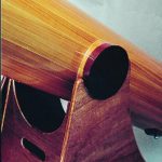
I used scrap cedar strips from the optical tube to fabricate two altitude pivots. I scribed the pieces to the outside of the finished tube, sawed and laminated them together. After they cured, I cut them into 6″ diameter circles. Next, I cut 6″ diameter disks from 1″ thick mahogany and bonded them to the spacers to extend the pivots. The mahogany portion of the pivot would rest on the mount’s bearings.
With all of the optical components installed, I hung the optical tube by a rope to locate the balance point. The center of the pivots was located precisely at this balance point, in line with each other on opposite sides of the optical tube. I used the top edges of the mold stations as a reference to align the pins, then bonded them to the sides of the tube.
Dobsonian mount
The mount holds the telescope steady and allows for smooth vertical and lateral movements. The mount has two parts, the rocker box and the ground board. The optical tube’s pivots rest on Teflon™ bearing pads in the yoke of the rocker box. The low-friction pads permit smooth, precise tilting, or rocking of the optical tube. The precise balance of the telescope lets you freeze the location, or adjust it with a slight nudge. This lets you easily follow an object as the Earth rotates. A pin on the bottom of the rocker box passes through an Oil-lite™ bushing in the center of the ground board. The weight of the rocker box and optical tube rests on low-friction bearing pads between it and the ground board.
The mount is constructed of ¾”-thick marine plywood glued and screwed together. Bonding will result in a more rigid and stable base. I attached a tray for eyepieces and filters to the supporting endpiece on the rocker box. The bearing surface of the rocker box is covered with plastic laminate. I spaced three Teflon bearing pads on the top of the ground board 120° apart and located them directly over the three legs for maximum stability. The ground board is round, its diameter is the same as the width of the rocker box so you don’t stumble over the ground board in the dark.
After using the scope a few times I discovered a couple improvements I’d like to make. As I observed objects more directly overhead, leverage for lateral adjustments of the scope is greatly reduced. I’ll be adding a lever, like a boat’s tiller, to the side of the rocker box to improve control and allow me to more easily steer through the heavens. When switching to a focuser with a different weight, the balance point shifts slightly forward. To compensate for this, I’ll apply an adhesive-backed magnetic strip to the back end of the optical tube. Then I will be able to add or subtract steel washers to precisely balance the telescope regardless of which accessory is attached.
Transport/storage case
I fabricated the telescope’s storage and transport cabinet around the mold I’d used to build the optical tube. The sides attach to sides of the three mold frames and the edge of the ¼” plywood bottom. I set wooden fillets on the inside corners between the stations. I built a 6″ tall lid and attached it with brass hinges. I glued felt padding to the three mold surfaces (now bunks) to protect the optical tube. Inside, I fashioned separate compartments for eyepieces, finder scope, sky charts and accessories, then varnished the interior.
Conclusion
I’m not an astronomer but this instrument makes me feel like one. I look into the sky and see more than what I thought were just stars. What I thought were stars are whole galaxies, greater than the Milky Way. What I thought was one star is actually two, revolving around each other. What was a white smudge in the dark sky is a collection of millions of stars. They fill the view through my telescope. An asteroid streaks through the view before my eyes; the sky is as alive with action as the sea.
You could buy a fine f6, 8″ Dobsonian telescope, ready to use, for about $500. For the dollar, it’s worth it. I spent many extra dollars on some premium items that drive the price up, but improve the view. I could have made it for less money, but I didn’t take on this custom project to save money. I completed the project in approximately 150 hours. It was a pleasure to build and more fun to use. I plan to have it around for more than a lifetime.
Sources
Optics
University Optics, —mirrors, cells, eyepieces
Orion Telescopes and Binoculars —mirrors, cells, eyepieces
Books
Build Your Own Telescope, by Richard Berry
The Best of Amateur Telescope Making Journal, Volumes 1 and 2, published by Willman-Bell, Inc.
Websites
Project costs
- Western red cedar and plywood . . . . . . $125
- WEST SYSTEM epoxy, 1½ Group A, with 206 Slow
- and 207 Special Clear Hardener. . . . . . $75
- Miscellaneous items
- (Teflon,plasticlaminate,screws) . . . . . . $25
- Secondary mirror . . . . . . . . . . . . $25
- Secondary mirror support . . . . . . . . . $30
- Primary mirror . . . . . . . . . . . . . $225
- Primary mirror support . . . . . . . . . . $30
- Focuser . . . . . . . . . . . . . . . $140
- Eyepieces . . . . . . . . . . . . . . $200
- Finder scope . . . . . . . . . . . . . . $80
- Finder scope bracket . . . . . . . . . . . $35
- Collimator . . . . . . . . . . . . . . . $35
TOTAL COST $1,025
The sun is magnificent to view through a telescope— but only with a filter. Building a solar filter for a telescope is pretty straight forward. See How to Make a Solar Filter for details.
WARNING! Never view the sun through a telescope without a filter. It can instantly result in permanent blindness.

