By Alphonso Peluso and his Spring 2014 IIT Architecture Students Joseph Bertucci, Cecilia Campos, Dijon Dunmore, Xinyun Huang, Jared James, Ryan Kim, Dakotah Lucas, Jeffrey McQuiston, Nick Rienstra, Teresita Pineda, John Seaman & Jeffrey Wigen
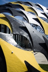
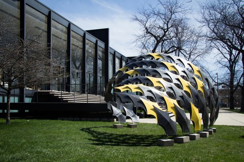
The FIBERwave PAVILION was designed and built as part of a student-based design research studio. Carbon fiber was used because when coated with epoxy it can become as hard as steel, and added layers enhance its strength. It offers designers great control over structural properties and is incredibly lightweight.
The pavilion is comprised of one geometric unit, “the shell,” repeated multiple times. The shell is extremely thin and lightweight with an overall thickness of 1/8” and weighs 1lb. The shell connects laterally at two points to another shell on either side with metal plates, creating flexible rows. The rows are then connected vertically by a bolted pin. A specific pattern of row length and vertical connections creates a curving wave-like structure called FIBERwave. The nature of the connections and the shell geometry allow the pavilion to undulate and morph.
The making of the 90 panels began by CNC milling a 44” long by 22” wide wooden male mold. To create the appropriate finish for releasing carbon fiber, .08” thick polystyrene plastic was vacuum formed over the mold. The maximum size of the vacuum former was 22” x 22” so it was necessary to cut the mold in half leaving two 22” x 22” sections. Each section was then vacuum formed and assembled back together (Photo 1).
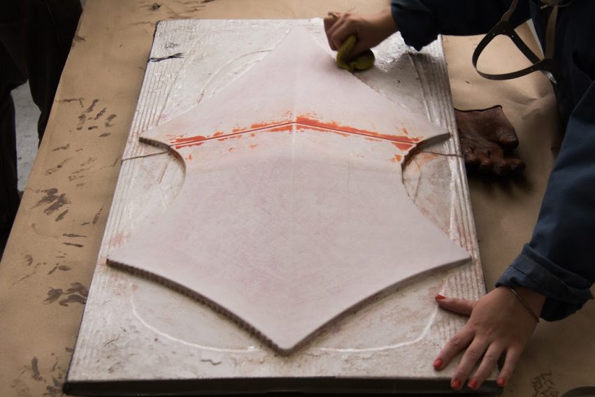
Next, the mold was prepped with several coats of Carnauba Wax and PolyVinyl Alcohol (PVA) mold release (Photo 2).
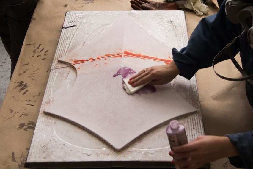
After the PVA was allowed to dry, WEST SYSTEM Epoxy 105 Resin and 205 Fast Hardener were applied to the entire mold (Photo 3).
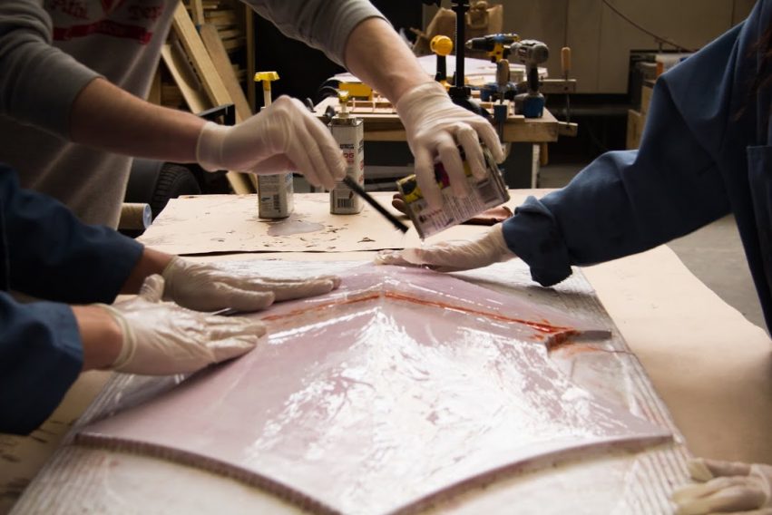
Next the first of (3) layers of 5.9 oz 3K 2×2 twill carbon fiber cloth was placed over the mold with the fibers running vertically at 90º and resin/hardener applied (Photo 4).
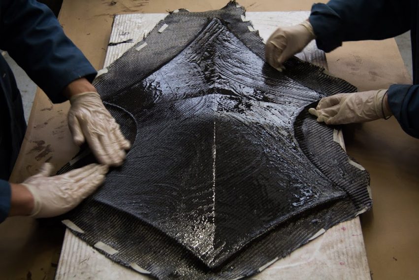
The next layer was a perforated structural foam core, this gave the panel the required strength at less cost versus additional layers of carbon fiber, then resin/hardener was applied (Photo 5). The whole process was repeated 89 more times. To save time and money the decision was made not to vacuum bag the 90 panels.
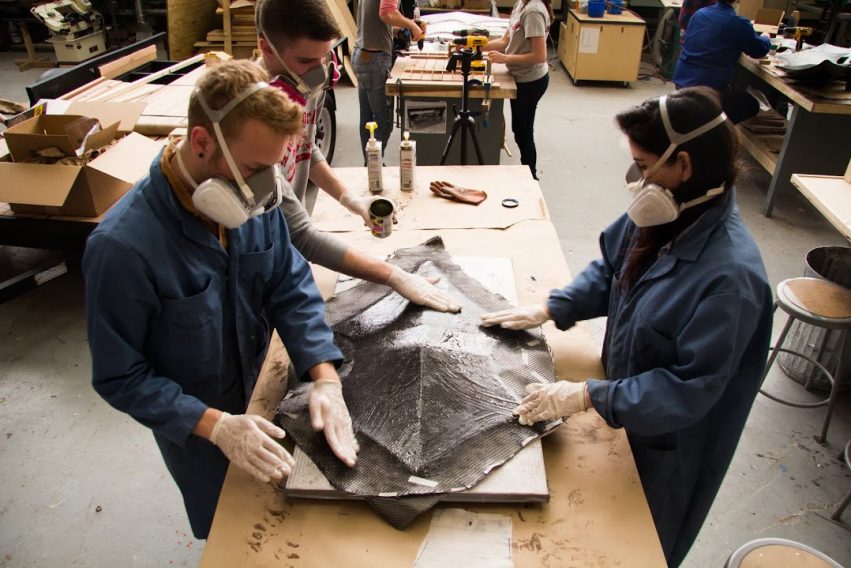
The remaining (2) layers of Carbon Fiber cloth were placed, the first with the fibers running at 45º and the second at 0º, both with resin/hardener applied (Photo 6).
Next, the top, bottom, and edges of the panel were sanded (photo 7). The whole process was repeated 89 more times. To save time and money the decision was made not to vacuum bag the 90 panels.
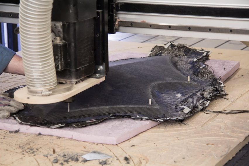
A total of six male molds were eventually made allowing six carbon fiber panels to be made per day. Once all the panels were made they were trimmed, sanded and finished. To precisely trim the 90 panels a foam mold that matched the six male molds was made. The carbon fiber panels were placed one at a time over the foam mold and the CNC machine trimmed and drilled holes in the panel (Photo 7).

As a last minute design decision several panels were selected to be painted bright yellow using exterior house paint. The painted panels along with remaining panels were finished with a clear coat of waterproof sealer.
