Replacing Core with Vacuum Bagging
Spring, 2025

GET STARTED
FREE PRINT & DIGITAL EDITIONS
Spring, 2025
When it rained, brown water leaked from the engine hatch and the mount for the cockpit table on my cousin’s 31′ powerboat. He keeps his engine hatch and cockpit covered when not in use, so there was no obvious point of entry for the leak. It was a mystery indeed. He asked if I could look at it and give him my two cents. This seemed like a perfect scenario to use vacuum bagging epoxy to help solve the problem.
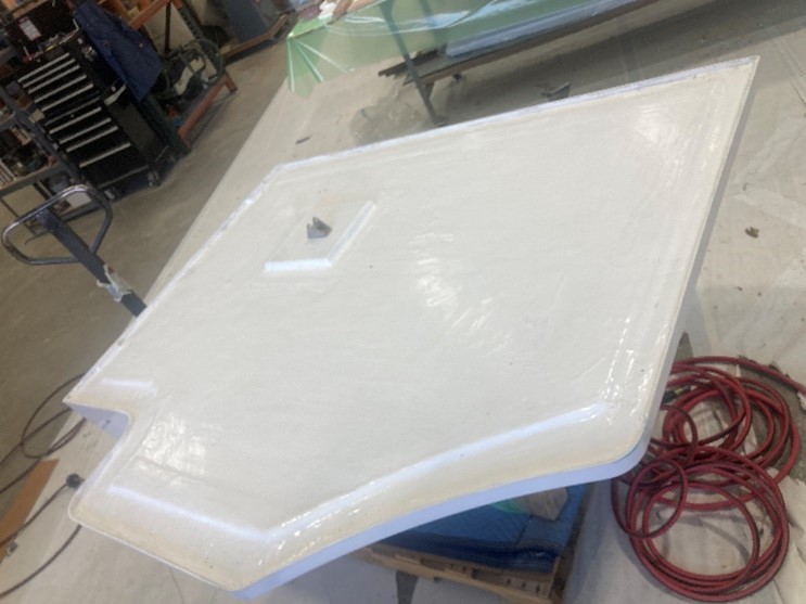
The engine hatch was roughly 5′ x 7′ with an integrated seat—the back of which faced the swim platform. The cockpit cover ended at the upper portion of the seatback, while there was an opening locker in the lower seatback. The locker door had a weather seal and corner drains inside the compartment to remove excess water splashed up from the swim platform. In addition to providing seating, the engine hatch served as the cockpit floor. The floor area had two four-inch holes in which table leg bases were installed.
The hatch was built as typically for a composite cockpit floor or deck. There was a finished, gelcoated layer of fiberglass (outer skin), a balsa/plywood core, and an inner layer of fiberglass (inner skin).
At the shop, I inspected the hatch for any areas of damage, or obvious sources of water intrusion. I removed the poorly sealed table leg bases and found no signs of water leaking from the top. With the bases removed, it exposed the two layers of ¾” balsa that comprised the core. The balsa was soaked with water, literally dripping out. When I pushed on the balsa with my finger, it crushed quickly, and water ran out like a squeezed sponge. Though this showed the apparent results of the water issue, I could not determine the cause.
The water saturated hatch required a fork truck to position the hatch on its side to easily asses the damage. I could begin my investigation by determining the moisture content. Next, I would weigh a sample of laminate and utilize a thermal camera..
Using a moisture meter every square foot, I took readings of the hatch. They ranged from 20-50% on the scale, including the areas that I could see were completely saturated with water. Moisture meters gauge the conductivity of a laminate. Higher moisture content increases its conductivity.
For my own interest, I also chose to do a weight comparison. I removed a wet 2.5 ft2 section of balsa and fiberglass. When first removed it weighed 124 oz. After the sample was allowed to dry completely, it only weighed 66 oz. That’s nearly half of the original weight!
Finally, I used a thermal camera to get an idea of how large an area was likely to be affected by this moisture intrusion. Thermal cameras are one method surveyors use to determine wet areas in need of repair. It is a noninvasive test that identifies areas where fiberglass skin should be removed to expose wet core, ensuring the repair remains minimal. I used one that plugged directly into my phone and that worked well enough.
Dry areas change temperature faster than wet areas. A thermal camera highlights the temperature differential between these areas after a recent temperature change. On a chilly morning, I rolled the hatch outside and let it sit for about an hour and a half. Looking at the thermal camera, we did not see what we expected. We expected moisture to be concentrated near a single entry point. However, we observed saturation throughout the entire hatch, with only a few isolated dry areas in the middle.
The thermal picture combined with the moisture readings made it clear that the entire core would need to be replaced. Though I hadn’t yet identified the problem’s source, I was hopeful that peeling back the inner skin would provide clarity.
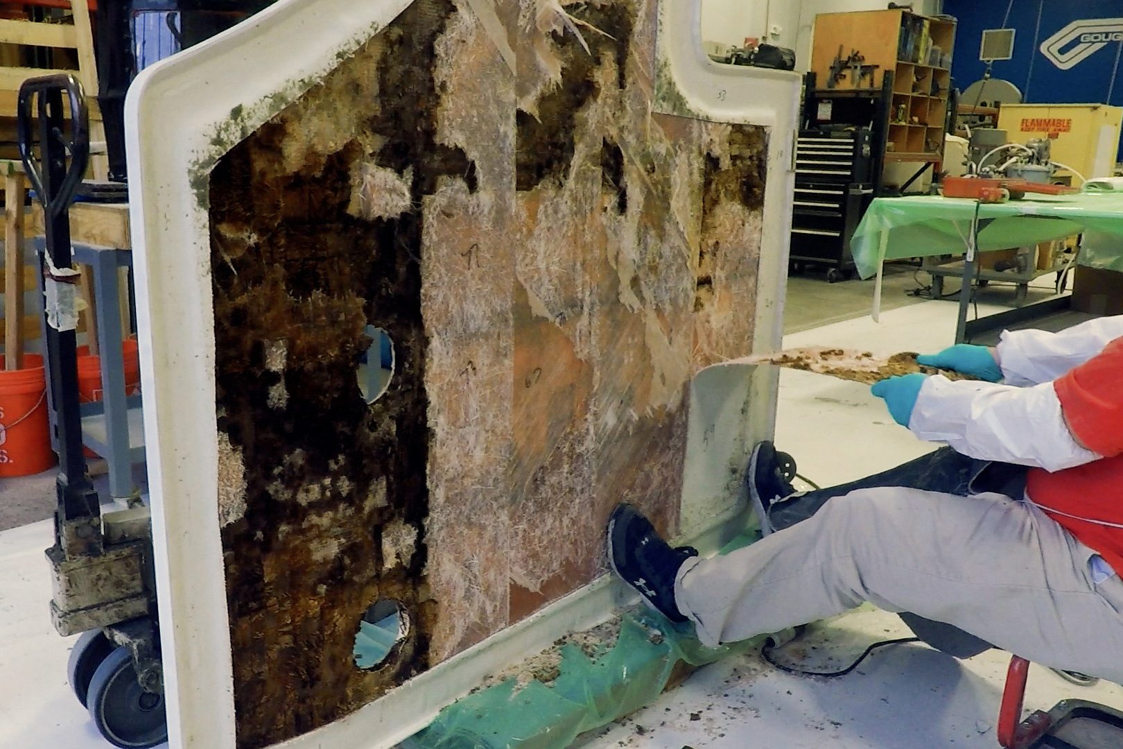
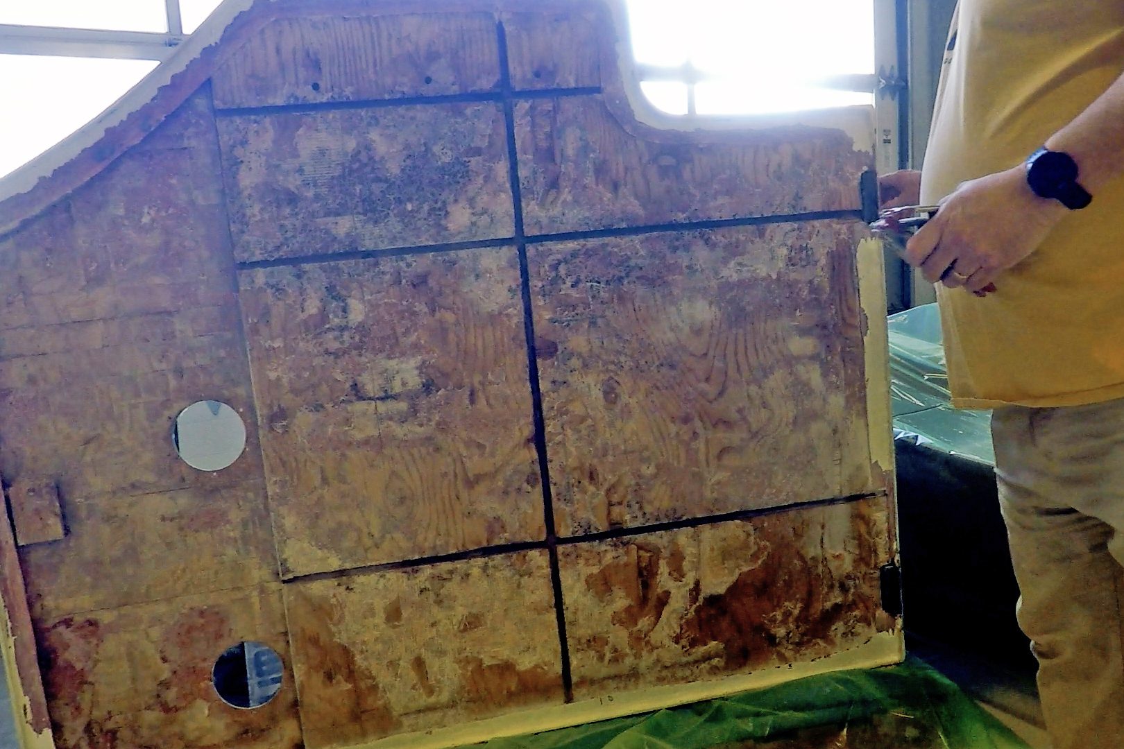
I cut the inner skin about 3″ from the edge of the hatch. This would leave enough of a tab of the inner skin to grind a bevel to overlap fiberglass onto when I was done. Next was removing the inner skin. I was hoping the core was rotted enough that I could remove it in one piece and reinstall it after replacing the core, but no luck. Cutting the skin into 1′ strips, I could peel and chisel it off. Exposing the rotted core, I could see there was a large grid pattern and the center of the grid was damp, but not completely rotted. This reflected what I saw with the thermal camera.
While removing the rotted core, I discovered roughly one-third of the hatch was two layers of balsa. The other two-thirds were comprised of one layer of balsa and one layer of ¾” plywood. The plywood had 1/2″ relief cuts in a grid pattern to allow the plywood to flex into the shape of the mold.
The relief cuts functioned as channels allowing water to flow easily through the hatch and soak the balsa core.
One of these relief cuts ended at the hinge for the engine hatch. The hinge had a backing plate that went through into the locker. Any water that got into the locker soaked into that backer block and drained into the relief cuts, flowing throughout the engine hatch. The weather seal had failed on the locker, allowing water to collect and soak into the backer before it could drain.
With the balsa removed, I was able to survey the plywood core. Other than dampness, and a few gouges from the balsa removal, it was in decent shape. I let it dry out for a few days, sanded the surface, and removed any remaining fiberglass from the surface. To clean the relief cuts and open up the end grain, I used a wire wheel on a drill and a router. I allowed the plywood to dry. Adding heat and/or a fan would shorten the overall drying time, but I had all winter. Every couple of weeks I would run the moisture meter across the plywood to make sure it was drying out.
While the plywood was drying, I began my prep work. First, I ground a 12-to-1 bevel on the fiberglass tab around the edge. By cutting into the bottom of the hatch, I would not have to do any gelcoat matching or color blending.
Utilizing 80-grit sandpaper, I sanded my bevel to smooth the grinder marks. Any exposed fiberglass from the upper skin was also sanded in preparation for bonding the new core. I dry-fit the new balsa core, marking alignment for easy reassembly.
I removed the plywood that was used for backers on the hinges and replaced it with Coosa® Board. Coosa Board is a high-density, polyurethane foam reinforced with fiberglass. This board eliminates any plywood end grain that is exposed to water inside the locker. Coated plywood would have done the job, but I was afraid the plywood coating might get damaged, allowing moisture to seep in.
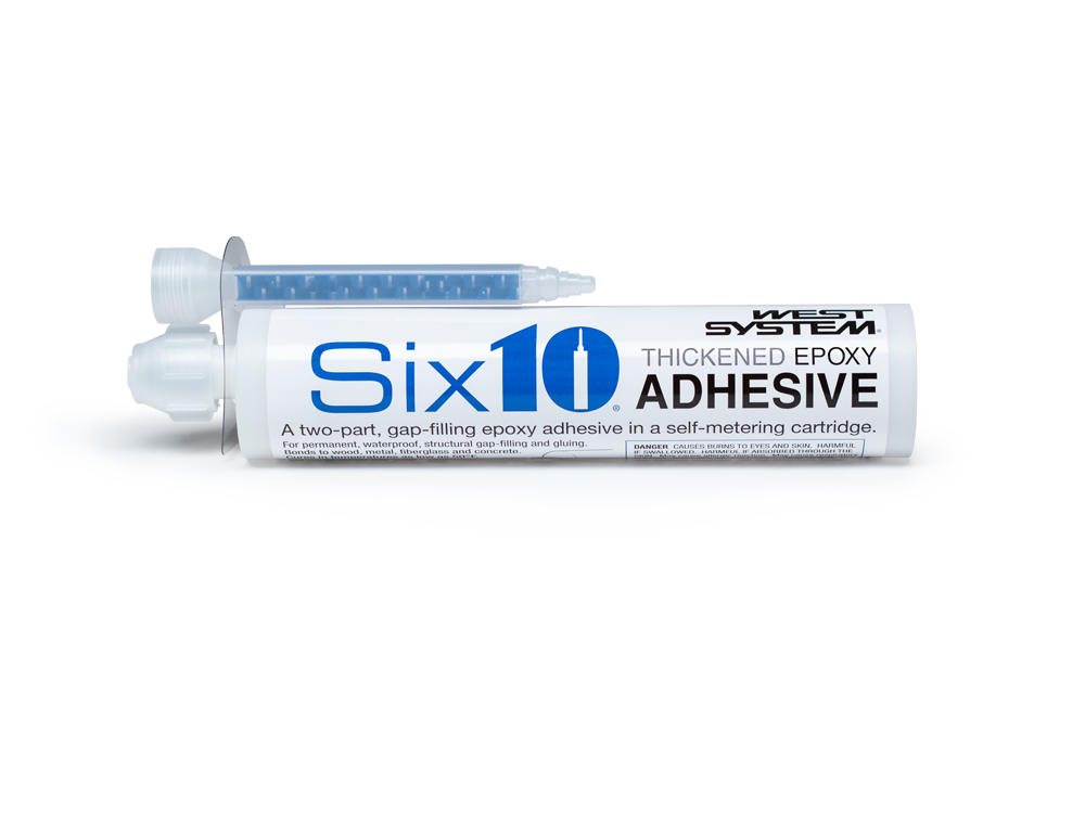
I drilled oversize holes for the hinge screws and used Six10® Thickened Epoxy Adhesive to fill them. Six10 is great at gap-filling with its thick and creamy consistency. It also worked perfectly for bonding the Coosa board backing block where the water was originally entered the core.
Finally, it was time to start setting up to vacuum bag. Vacuum bagging sounds more arduous than it is. While it does require extra prep work, it is a great way to hold an even clamping pressure across a large surface. Even clamping force ensures great contact between the core and outer skin, minimizing voids and reducing water intrusion risk.
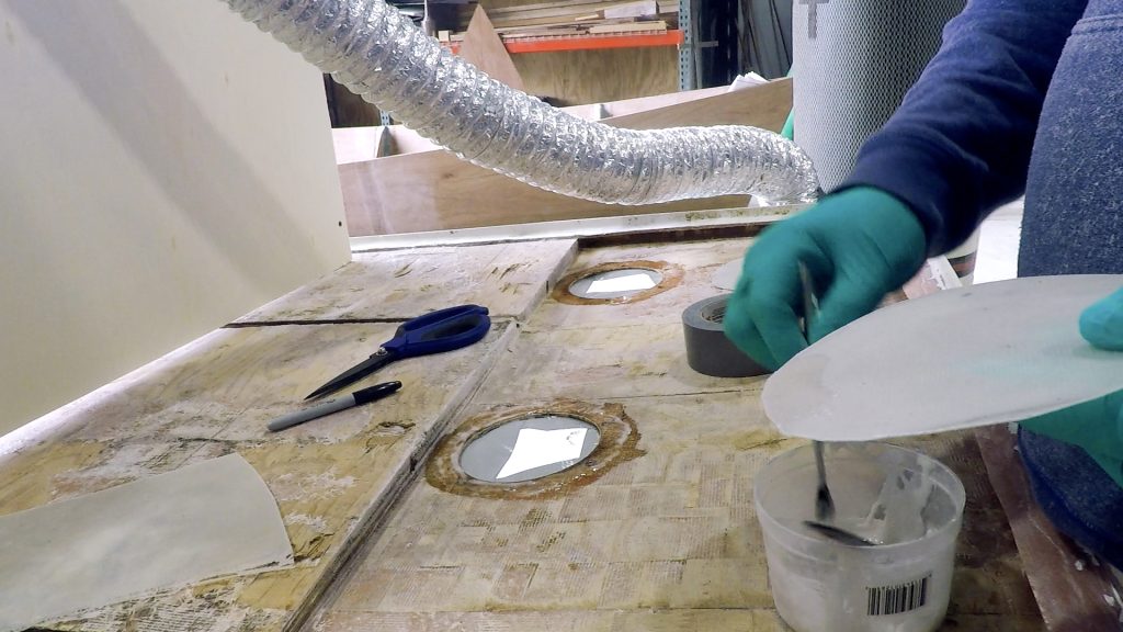
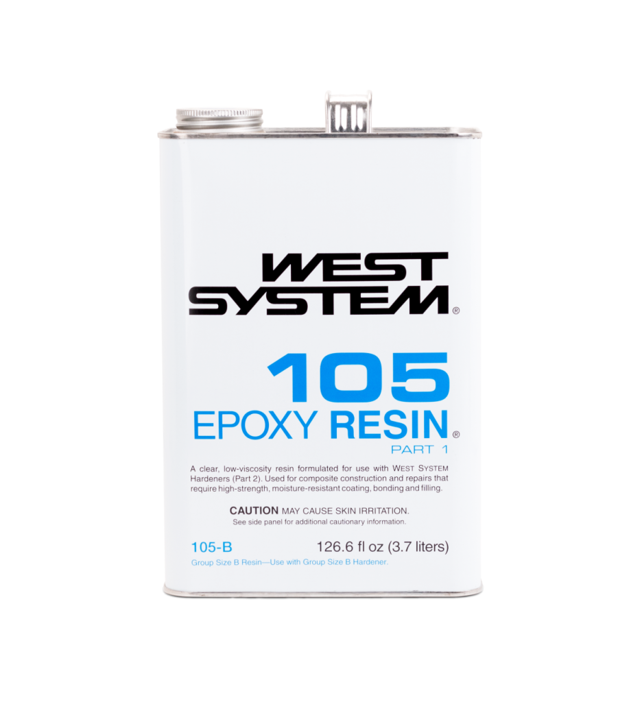
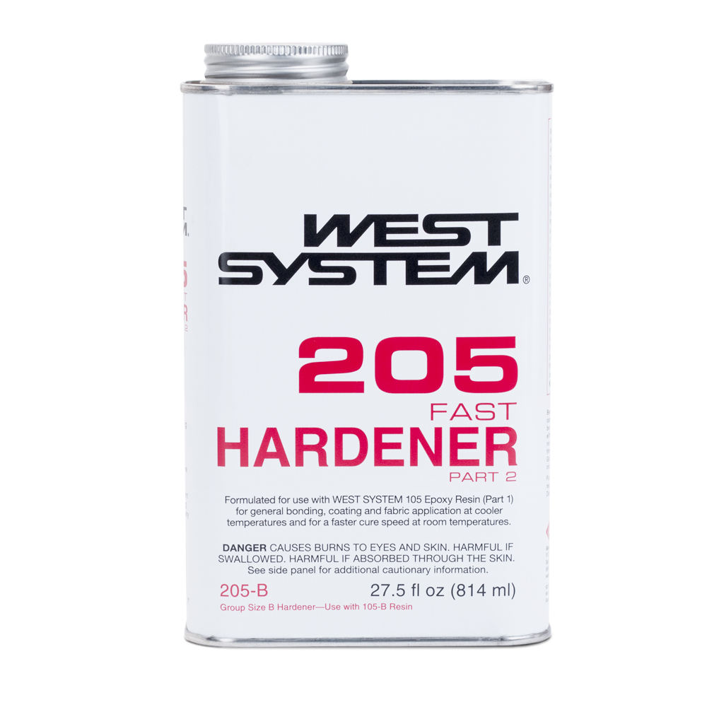
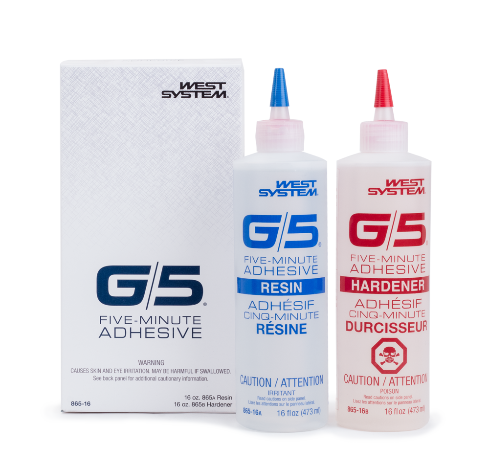
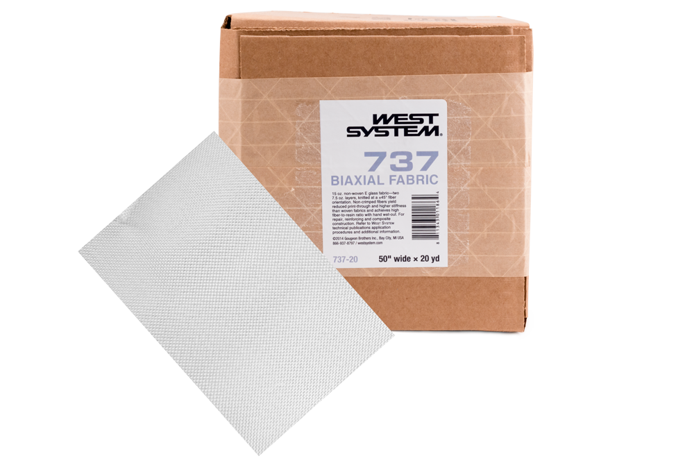
The top skin needed to be airtight for the vacuum to work properly. Using two layers of our 737 Biaxial Fabric, wet out with 105 Epoxy Resin® and 205 Fast Hardener®, I made fiberglass laminates to use as cover plates for the table support openings. G/5® Five-Minute Adhesive worked great to bond them inside the outer skin quickly.
Then I applied the Vacuum Bag Sealant around the outside perimeter of the hatch.
With the shop temperature in the low 70’s (°F), and the prep work completed, it was installation time. To start, I rolled the hatch upside down to create an easier working surface. Since this was a bigger project, I chose to work with the WEST SYSTEM® 209 Extra Slow Hardener®. When combined with the WEST SYSTEM 105 Epoxy Resin, it would give me 3-4 hours of working time to get the core coated, put in place, and the vacuum bag on. Working alone, I would surely need all this working time. Luckily for me, just as I started, fellow Technical Advisors, Don and Greg, offered to join in the fun.
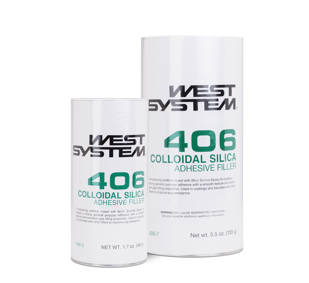
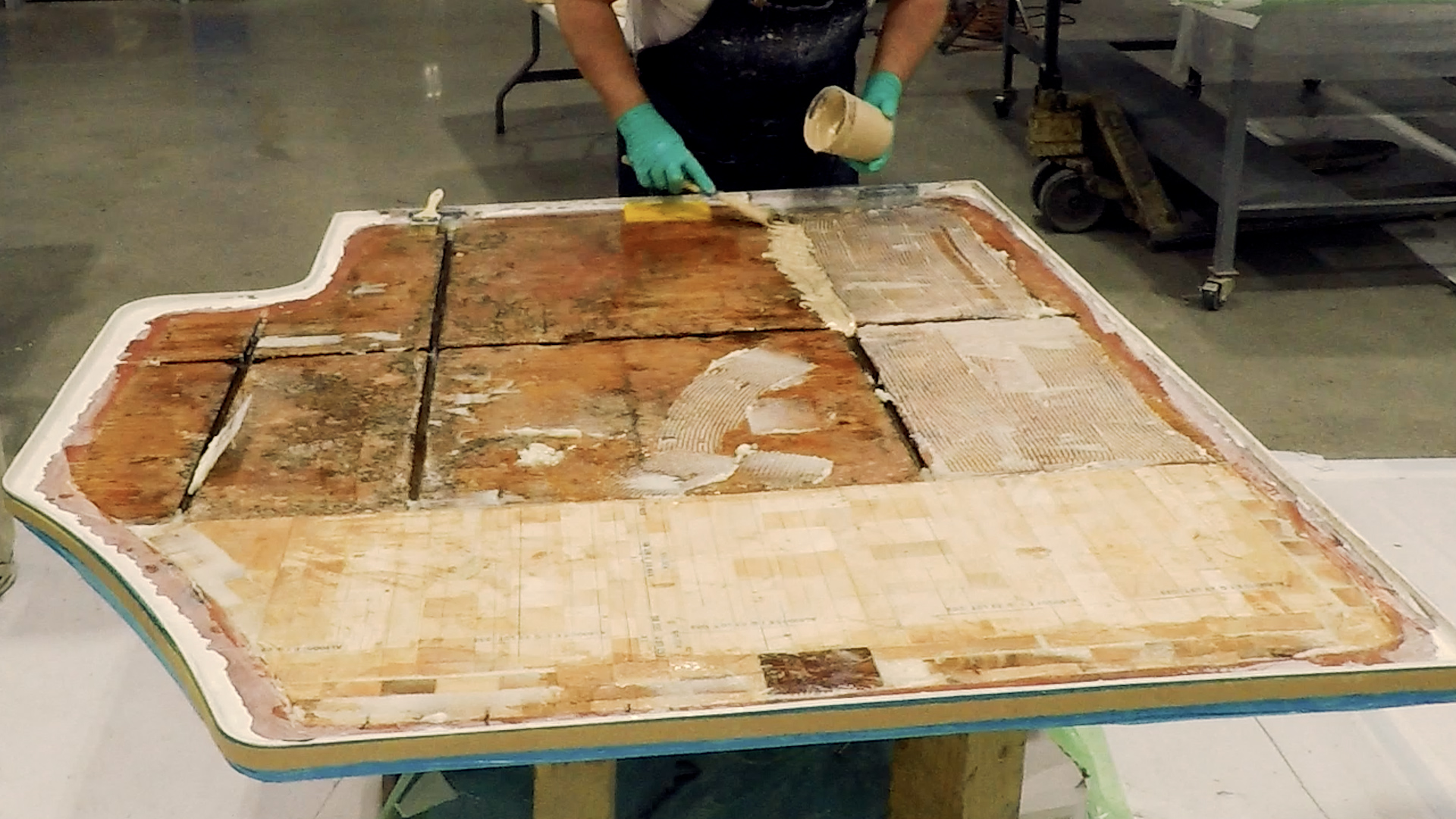
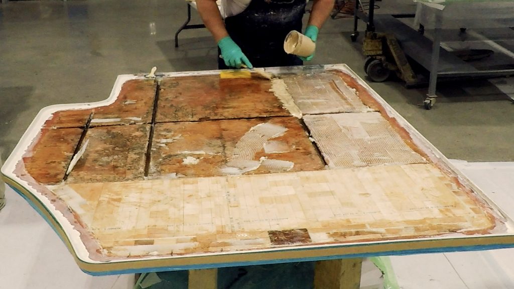
We coated the plywood and the back side of the outer fiberglass laminate with unthickened 105 Epoxy Resin and 209 Extra Slow Hardener. Don started mixing 406 Colloidal Silica into the epoxy to create a catsup consistency. He troweled this mixture over the fiberglass, laying a bed of epoxy for the balsa core. Mixing a little thicker batch, he used it to fill in the corners and near the edges where the balsa core wouldn’t be able to reach.
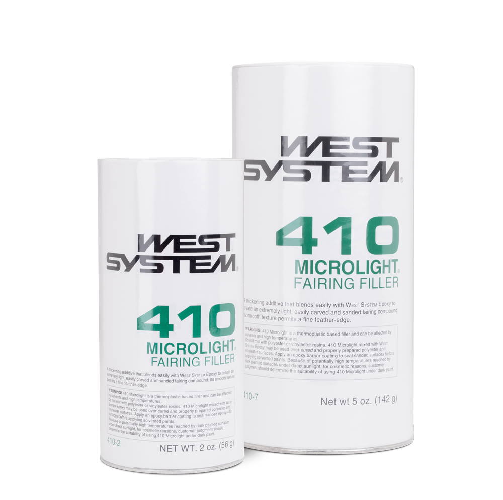
While Don laid the epoxy, I coated the balsa core with unthickened epoxy, and Greg filled gouges in the plywood with epoxy and 410 Microlight to prevent water migration, Fig. 4.
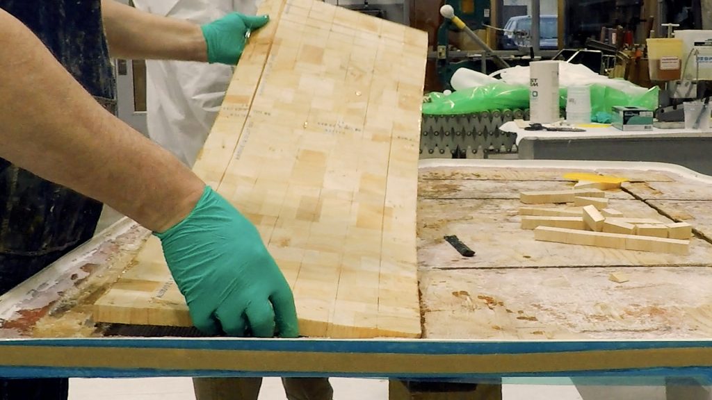
We installed the first layer of balsa. Any remaining gaps were filled with epoxy thickened with 406 Colloidal Silica. The first layer only needed to cover about one-third of the surface area of the hatch due to the plywood layer. Now we were ready for the second layer of balsa which would cover the entire area.
Greg and Don coated the plywood and the first layer of balsa with a catsup consistency of epoxy mixed with 406 Colloidal Silica. I simultaneously applied a neat coat of epoxy to the balsa core side that would be mating with the first layer of balsa and plywood. The top side of the balsa would be coated later when we applied the fiberglass. The alignment marks from dry fitting made quick work of installing the second layer of core.
We draped 879 Release Fabric over the balsa and out to the edge of the hatch. Release fabric does not stretch so you must make sure to tuck it into corners and valleys to prevent it from bridging. The bridging holds the vacuum bag off the surface, creating air voids that will collect extra epoxy and may leave hard spots. These pockets of epoxy can also generate too much heat from the exothermic reaction.
Over top of the release fabric, the next layer would typically be perforated film to control epoxy content. For this project it was not a concern, so I skipped it. We draped the 881 Breather Fabric over top of the release fabric. The breather fabric allows air to move freely under the film towards the vacuum pump.
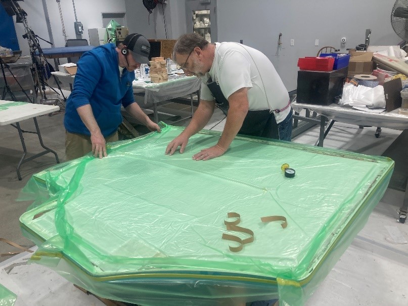
The final layer to seal the envelope was the 882 Vacuum Bag Film. Even though this was a flat panel with minimal contour, I still cut my bag approximately 1.5 times the size of the overall hatch. The bag had to be large enough to fit tightly into the contours. The core only steps up about 3/4″, but it is better to have too much film than not enough. I peeled the paper backing off my 883 Vacuum Bag Sealant that I had adhered around the perimeter of the hatch and applied extra to seal any pleats or folds in the bag film.
The end of the vacuum tube, wrapped in a bundle of breather fabric, was inserted through one of the pleats before being sealed closed. The other end of the tube connected to a “T” before continuing on to the vacuum pump. I added the “T” to attach a valve. Our vacuum pump in the shop can pull 29 plus inches of mercury (29″ Hg). By adding the “T” into the vacuum line, I could control the vacuum, bleeding it down to about 5 inches of mercury (5″ Hg or roughly 2.5 psi) (See vacuum bag techniques 1.2).
For our engine hatch, we have the convenience of working at table height, however that is not always an option. One of the great things about vacuum bagging is that it applies the same pressure on all surfaces underneath the bag. This holds true whether the surfaces are horizontal, vertical, or even inverted.
With my bleeder valve mostly open, it was time to turn on the vacuum pump. As the vacuum bag was slowly pulled down onto the hatch, we adjusted the bag so there was enough slack for it to follow the contours of all the corners, preventing bridging. Once satisfied, we added a vacuum gauge on top of the breather fabric opposite the vacuum line. Then we slowly closed the valve until the gauge read 5″ Hg. We checked the vacuum bag for air leaks.
It is important to keep the vacuum pump on until the epoxy has become firm. This period can vary, depending on the choice of hardener and the temperature. In this case, with the 209 Extra Slow Hardener, I kept the vacuum on overnight.
The following day I removed the vacuum bag, breather fabric, and release fabric (all one-time-use products). The release fabric can be left on for days and even weeks at a time to keep the repair area clean until you’re ready to move on to the next step. In this instance, it was time for the release fabric to be removed as well.
I used a small grinding wheel to smooth imperfections from the vacuum bagging and freshen up areas of my 12-to-1 bevel with epoxy. The new layers of fiberglass would be adhered to this edge. I slightly beveled the top edge of the balsa core as well to help the fiberglass roll over the edge.
I had precut five layers of 738 Biaxial Fabric, giving me a thickness of just over one-eighth of an inch to match the laminate I had removed. The roll of fiberglass was not wide enough to cover the entire surface in a single piece, so each layer was made from two pieces butted together. The seams were staggered for a stronger joint. Even though I wasn’t planning on vacuum bagging the fiberglass I still used the 105 Epoxy Resin and 209 Extra Slow Hardener for the longer working time.
With help from Don and Greg, we started by coating the balsa core with unthickened 105 Epoxy Resin and 209 Extra Slow Hardener. We then thickened the mixture to a mayonnaise consistency with 406 Colloidal Silica and applied it around the edges to make fillets. This would help the fiberglass transition over the 90° corner where the core met the flange. Then we coated the entire repair area with 105/ 209 slightly thickened with 406 Colloidal Silica. This filled in any imperfections and made a nice base for laying our first (and largest) layer of fiberglass.
We used an 808 Flexible Plastic Spreader to work the fiberglass into the epoxy, adding more epoxy as needed to wet out the 738 Biaxial Fabric. After saturating the first layer, we added four more layers of fabric, from largest to smallest.
Just like our vacuum bagging stage, we used 879 Release Fabric over the top. When using release fabric for a hand layup project, I use the 808 Flexible Plastic Spreader to work the fabric into the epoxy. The goal is to have no visible white spots remaining on the release fabric. If the epoxy has soaked in properly, the fabric should go translucent and all that should be visible is the thin red tracer lines. These red lines allow you to easily tell if you have removed the fabric entirely. After letting the epoxy cure for a few days, I removed the release fabric and used a small grinder and sander to remove imperfections.
We had our choice between paint or gelcoat for the final finish on this project. I prefer a gelcoat finish in an engine compartment as it performs better in the event of a spill. When buying gelcoat, there are two basic types. The first is finish gelcoat with a wax additive that cures to a hard finish. The second is laminating gelcoat, which cures to a tacky finish for additional layers. For this project I used the finish gelcoat and brushed it on heavily.
After the gelcoat dried, I flipped the hatch over onto sawhorses and used a jigsaw to cut out the openings for the table leg bases. I wanted to make sure that if these bases ever leaked, water wouldn’t reach the core of the engine hatch. To achieve this, I removed about 1/4 inch of balsa wood from between the skins all around the openings. I then filled that space with Six10 Thickened Epoxy Adhesive to seal off the core.
After numerous hours of labor, and roughly $800 in materials, the hatch looked almost the same as the day it was delivered for repair. A noticeable difference, however, was the weight. We were now able to hand lift the hatch onto the trailer without the use of a fork truck.
This was a substantial project with hours of messy labor, but it is a far more approachable project than it seems at first glance. Replacing the core from the underside allows you to avoid the finish side gelcoat color matching and application. The addition of vacuum bagging makes for a terrific way to save time and hold materials in place and get consistent clamping pressure as the epoxy cures. When combined, these techniques make for a great cost-saving DIY project.
Check out Terry’s video on restoring the rotted balsa core of this engine hatch, utilizing vacuum bagging techniques.
Learn more vacuum bagging basics!