

By Ken Wilson
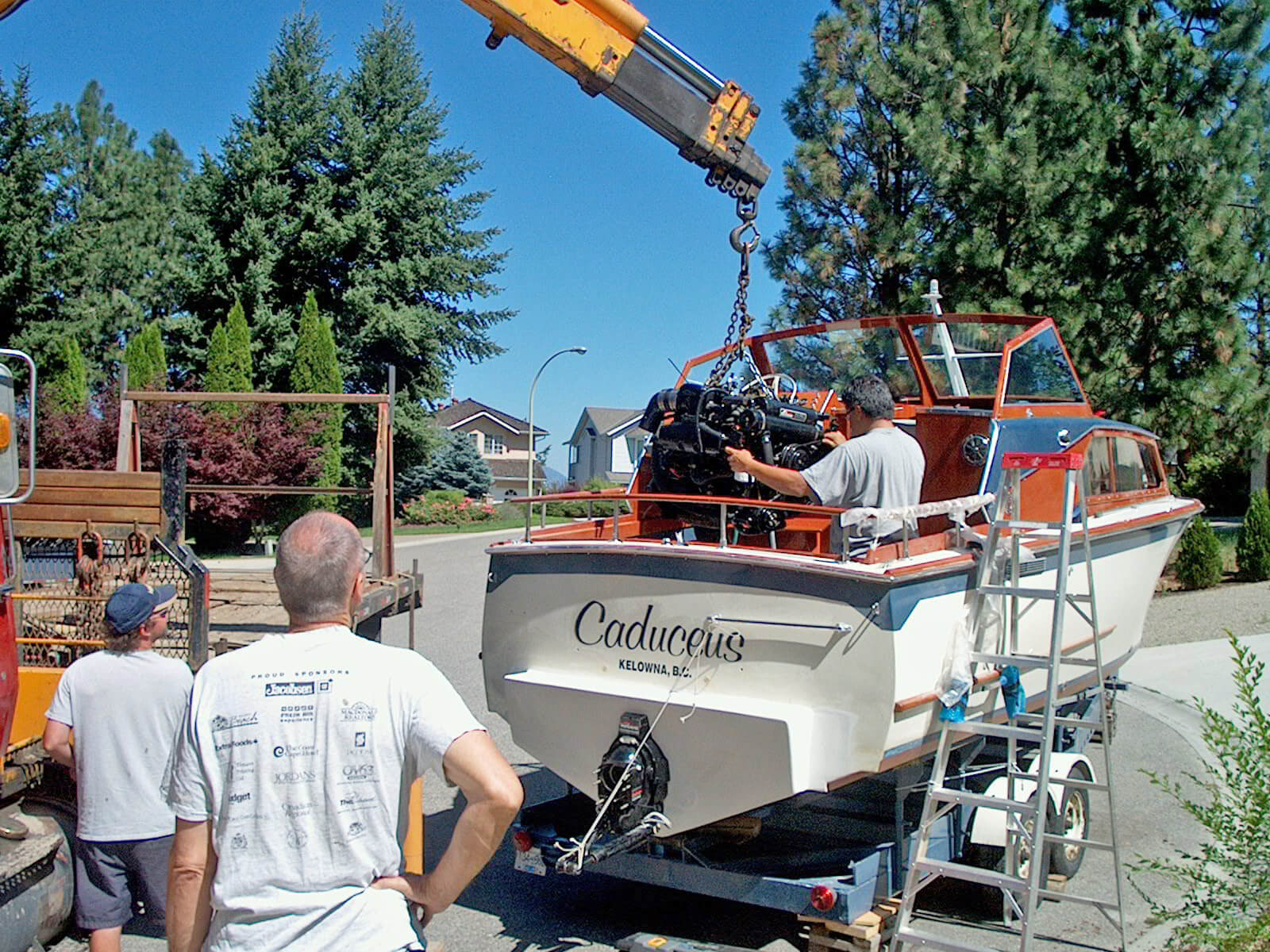
After burning out my engine coupler and being towed home to Kelowna Yacht Club (KYC) (by a sailboat, no less), I knew my boat was going to need some work. We hauled the boat out of the water and removed the engine to determine the extent of repairs required.
I have an Enos custom built fiberglass hull cruiser that my dad commissioned in Vancouver, British Columbia, back in 1964. Now, nearly 60 years later, we continue to enjoy the boat, spending much of our time on Lake Okanagan.
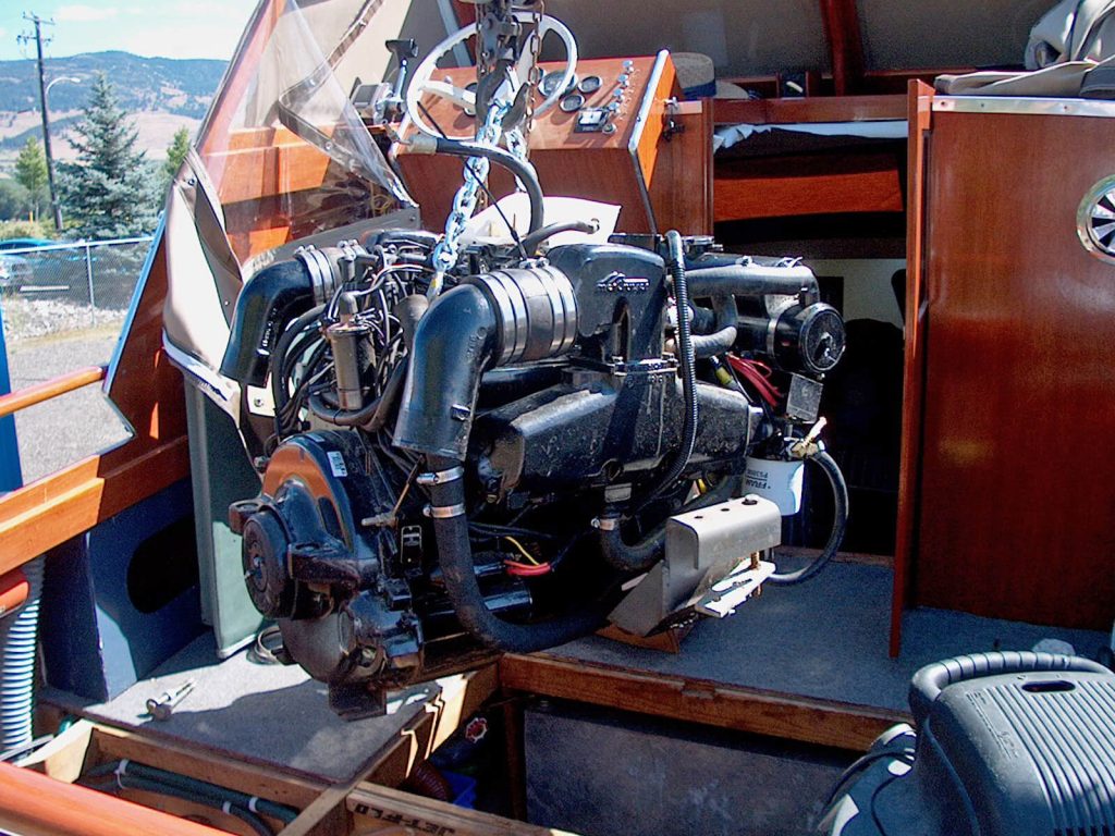
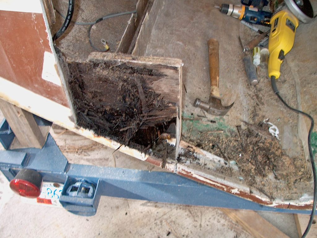
With the engine (a 5.7-liter Mercruiser Bravo II) removed, I could tell there was more damage than just the burned-out coupler. The last ten feet of the stringers supporting the motor were rotted and would need to be replaced. Also, the oil pan was rubbing on the inside of the keel, indicating the transom didn’t have enough angle to properly accommodate the motor.
I made prototype engine bearing stringers to use as an engine stand in my garage so I could work on the engine over the winter. Then I installed a new engine coupler, new water pump impeller, and power steering cooler hose.
Developing a Plan
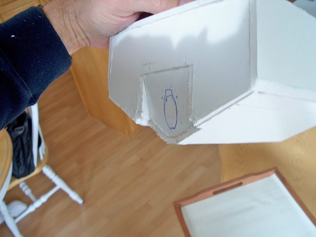
With spring not quite here yet, it was time to research the best approach for repairing the stringers and adjusting the transom’s pitch. I consulted the WEST SYSTEM® manuals and The Gougeon Brothers on Boat Construction book to develop my approach. Additionally, I consulted the book Fibreglass Boats by Hugo Du Plessis and, of course, the internet. Armed with my knowledge, I formulated my plan.
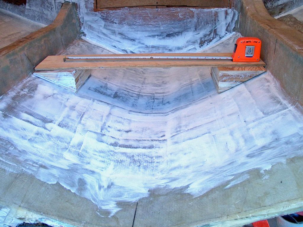
I built a model of my plan. Instead of the transom section protruding at the top, like it was currently doing, I wanted to have the top flush with the rest of the transom and tip the bottom section in to accommodate the angle the motor needed. I adjusted the model until I was happy with the angle. This plan would also require moving the first bulkhead forward to accommodate the engine.
Cleaning and Demolition
It’s time to get to work. Cleaning forty years of oil and bilge water took forever. After scrubbing with grease removers and soap, I power-washed, then used solvents and acetone. I allowed the fiberglass to dry over the fall, winter, and spring before giving it a final sanding and acetone wash.
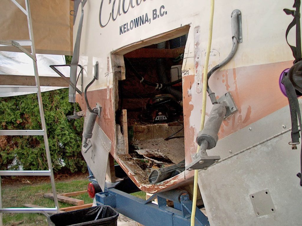
With ski season over, the transom and stringer work could start. I had to remove the existing, protruding angled section around the motor opening. I ground a channel through the outer fiberglass skin to make cutting easier. This project was a big commitment, so I bought several new tools, including a 12-amp reciprocating saw. My Thule® box made a perfect overnight storage area for my tools and supplies.
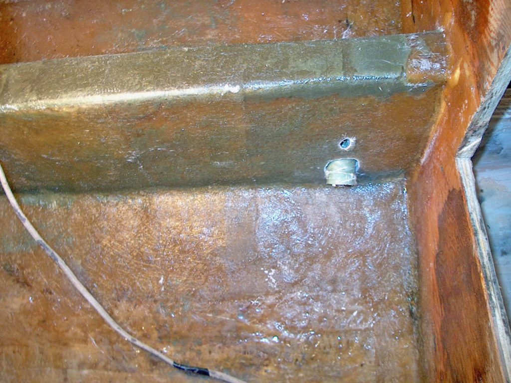
The stringers inside the boat were cut down leaving, 4″ of fiberglass tabbing protruding from the hull. All the rotten wood core material was removed.
Plans Change—The Hole Gets Bigger
The wood core of the transom around the removed area was pretty solid, but not everywhere. The rot got worse towards the ends of the stringers. I suspect water was collecting between the stringers, and due to a lack of limber holes, it had nowhere to go, filling up the cavities. Over time, the water worked its way into the stringers and traveled through the wood all the way back into
the transom.
The rot needed to be removed before rebuilding could begin. I had to cut a larger opening in the transom to get to the edge of the rot. The rot was worse near the stringers, especially on the port side. The stringer core needed to be removed from the transom to the first bulkhead forward of the engine. This big job was undertaken with a chisel, hammer, saws and lots of patience.
At this point in the project, I changed my mind and did not want to move the bulkhead. That meant I would have lost storage space forward of the bulkhead and would have to do a lot more work. Therefore, the transom section must remain flush at the bottom and tip out at the top.
New Stringer Core
I spent many hours cleaning and fairing the bilge area to prepare for the new core and, eventually, more layers of fiberglass. This included thoroughly preparing the 4″ fiberglass tabbing left from the previous stringers and the hull surface between them.
The new stringer core was made from two pieces of ¾” marine grade plywood epoxied together. All of the wood was first warmed and then encapsulated with unthickened (neat) epoxy using WEST SYSTEM® 105 Epoxy Resin® and 206 Slow Hardener®. Special attention was given to all end grain to ensure it was sealed with epoxy. The stern ends were cut at an angle, ready for attaching to the new transom piece.
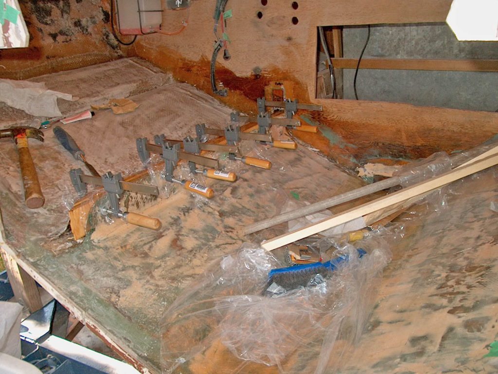
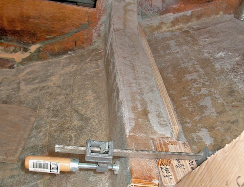
Thickened epoxy was applied to the inside surfaces of the stringer tabbing and the hull. The laminated core was then inserted. Lots of plastic sheeting was used around the bond area to prevent epoxying the clamps to the stringers. I used many clamps, tightening them until they were secure, but not so much that I squeezed out all the epoxy.
New Transom Core
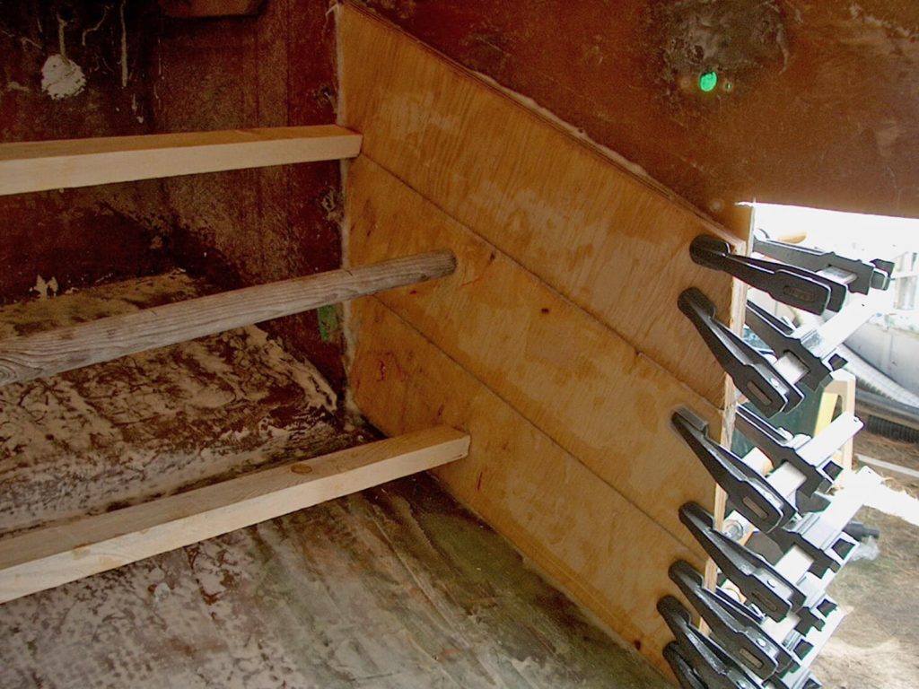
With the stringer core installed, it was time to rebuild the transom. The transom has a concave (looking from the inside) curve, making it very strong. To keep the curve, I epoxied the first layer of ¾” plywood in sections. I needed to be sure there was good contact, without any voids, across the surface of the fiberglass transom. To have ample working time, I used 206 Slow Hardener and only installed one section per side per day.
I braced the plywood against the bulkhead with long scraps of wood. Along the opening in the transom, I used lots of clamps. I tightened the clamps to avoid epoxy-starved joints to a pressure similar to a firm handshake. I used plastic sheeting everywhere to avoid gluing my clamps to the boat.
With the temperature starting to drop as we got closer to fall, I found it helpful to use a radiant heater to warm the substrates before epoxying and fiberglassing.
Once the planking was done on both sides of the transom opening, it was time to add my plywood reinforcement above the transom opening. I made a special effort to use one piece of plywood across the top of the transom opening for extra strength. I used several layers of 5/16″ plywood because it was easier to work with than the ¾”. I first bent the plywood, then epoxied the pieces in, one at a time, to fit the curve of the transom. It worked very well. No voids and good adhesion. I used braces and lots of clamps to hold the plywood in place while the epoxy cured.
Limber Holes
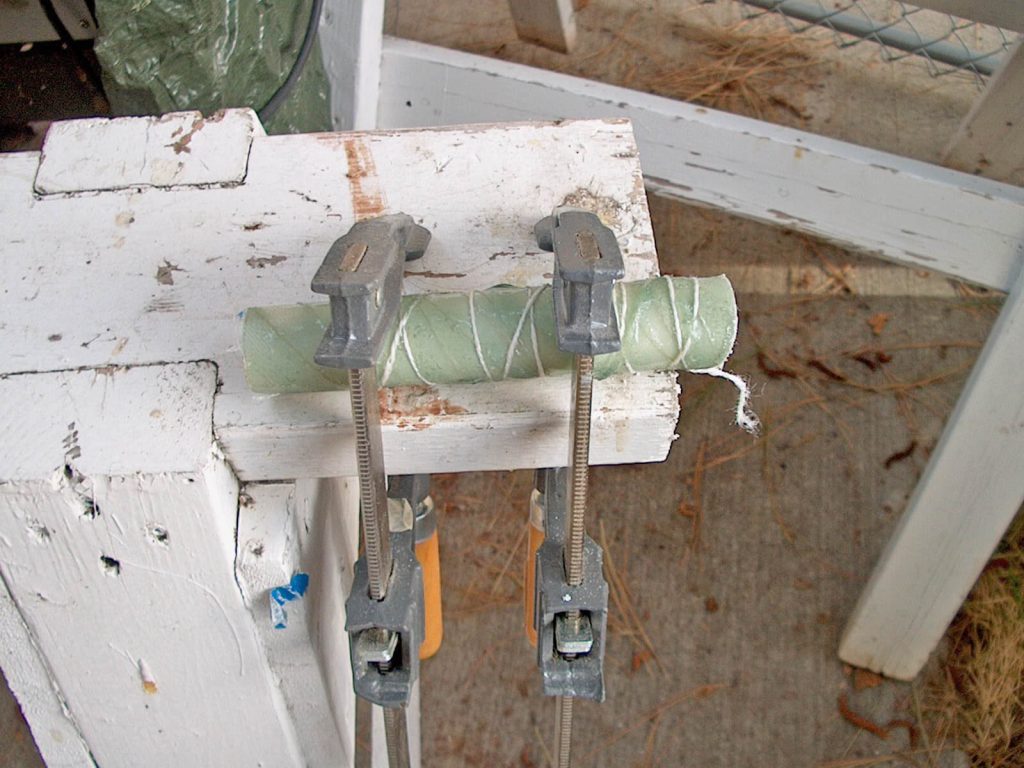
I rebuilt the stringers with limber holes so water can’t collect behind them and cause rot again.
I used a 1″ PVC pipe wrapped in fiberglass to create the tubing for my limber holes. I started with a section of pipe long enough to use for all my limber holes. I wiped the tube with acetone and roughed it up with coarse sandpaper to prepare the surface. I wrapped the tube with fiberglass cloth tape and unidirectional fiberglass. I wound a length of string around the assembly to hold the cloth tight to the tube. Once cured, I cut the tube into the lengths I needed for each of the limber holes.
This method of fiberglass wrapping the PVC will ensure good adhesion of the PVC to the stringer. If the PVC were to break loose from the stringer, water could penetrate the stringer core again.
To install the PVC/fiberglass limber hole, I drilled an oversized hole through the stringer for the limber hole tube. I also drilled a much smaller hole above this, angling downward—exiting through the tube hole in the middle of the stringer. I then inserted the limber hole tube and laid up strips of fiberglass mat in the gap between the oversized hole and the tube. This sealed the opening on both sides of the stringer. Once that had cured, I injected neat epoxy through the small top hole into the space around the pipe. This should ensure a good bond and seal out water if that bond should ever fail.
Reinforcing the existing transom was almost finished. I then covered it with four layers of biaxial fiberglass and three coats of epoxy. The natural wood looked so good I was tempted to leave it, but I finished it off with three coats of white epoxy paint.
Checking the Bilge Keel Cap
Since I had everything torn apart and discovered the extensive stringer and transom rot, I cut off the bilge keel cap. I wanted to expose the wood keel and check that for rot too. Luckily, there was none. I dried the keel for six months (over the winter), then coated the warmed keel with neat epoxy to prevent future rot. I replaced the cap pieces and filled the gaps with thickened epoxy. I covered the area back up with a layer of fiberglass CSM, unidirectional fiberglass, bi-directional fiberglass, and a layer of CSM again.
Stringers and Transom Knees
I wanted to strengthen the stringers that were located either side of the motor and add transom knees to help transfer the load from the transom to the stringers. I increased the width of the stringers by sistering them with a total of three pieces of ¾” plywood.
The plywood was double-coated with epoxy to form a waterproof barrier. Then, it was bonded in place. The ends of the plywood were intentionally left staggard. This allowed the knees to be aligned more easily during installation, and the staggered joints ensured a smoother load transition from the transom into the stringer.
I applied fiberglass to the stringers, leaving the ends exposed for later. Two layers of unidirectional fiberglass cloth were followed by three layers of bidirectional fiberglass, and the top of the stringer received extra layers of fiberglass.
The knees were built from three layers of ¾” marine grade plywood, epoxy coated and bonded together.
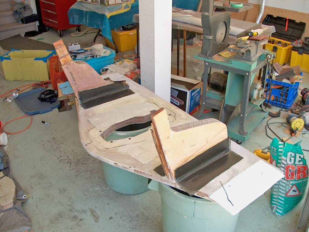
Transom Extension
In the spring of 2007, with the snow melting and ski season done, it was time to break back out the epoxy. I needed to extend the hull bottom for the new transom to sit on to keep everything in perfect alignment.
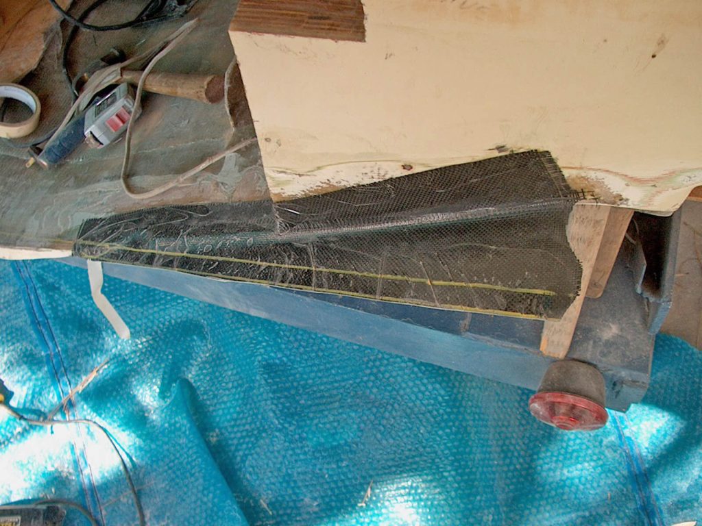
I started by building a supporting plywood platform that extended the lines of the hull aft. I covered the platform with a plastic drop cloth so the epoxy would easily release later. My first layer was carbon fiber. I laid it on the plywood platform and wrapped it a couple of inches onto the existing transom. Next, I applied two layers of “S” biaxial fiberglass cloth and another layer of carbon fiber. I allowed that to cure, removed the platform, and then trimmed the new extension to size.
With the platform removed, I now had access to reinforce the bottom of the fabric/transom seam, tying the hull and extension together. The reinforcing fabric had to taper onto the hull to evenly distribute the loads. I ground ½” of thickness off the 1″ thick original hull laminate at the seam. Then I tapered away from that seam about 6″.
I made a template of the tapered area on a piece of 6-mil polyethylene sheeting. I marked the different sizes of the layers of fabric that would need to be cut to feather the patch evenly into the hull. Then, I cut out all the layers of carbon fiber, Kevlar®, and “S” biaxial fiberglass cloth.
Kevlar is very difficult to cut compared to carbon fiber and fiberglass; however, like carbon, it wets out very easily. I wanted Kevlar because it will provide good abrasion resistance. The last layer was biaxial fiberglass so I would not have to sand the Kevlar.
I made a piping bag out of a Ziploc® bag and squeezed out the thickened epoxy to make a neat fillet. After rounding the fillet, the small lines were scraped away before the epoxy dried. No mess, no waste.
At this point, the extension’s thickness was ½”. There was another ½” to go. I built up more layers (top and bottom) of fiberglass, Kevlar, and carbon to reach 1″ of thickness.
Building the New Transom
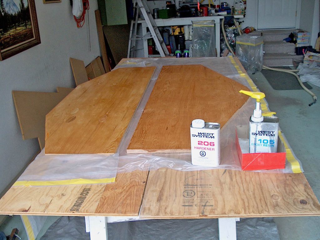
Now, it was time to start building the new vertical transom surface. I used my prototype template to cut out two pieces of ¾” marine-grade plywood. I laminated the two pieces together with a layer of fiberglass in between.
At this point I had spent over $1,000.00 (CA) on WEST SYSTEM Epoxy and fillers. In the end the total ended up being over $1,600.00 (CA). It was well worth the money for as much bonding and laminating as I did in this project.
I put a layer of polyethylene sheeting on the new hull extension and covered it with thickened epoxy. I bedded the newly laminated transom piece in the thickened epoxy. This ensured a perfect fit and placement when I was ready for the final installation. After it cured, I peeled the sheeting off, leaving the epoxy bonded to the transom.
I temporarily reinstalled the new vertical transom piece, which allowed me to position the motor’s transom plate and mark where I would need to drill my mounting holes. At this time, I also marked on the stringers where the motor mount pads should be located.
My rented drill made quick work out of the holes for the motor transom plate. A jigsaw was used to cut the opening in the transom for the motor. New saw—quality blades. No problem.
The Motor Mount Pads
I laid a few more layers of fiberglass between the stringers to help tie the stringers together and reinforce the hull for the new motor mount pads. These ran along the hull from the transom up to the first bulkhead.
The motor mount pads were built from four pieces of ¾” marine-grade plywood, epoxied together into one rectangular block. I sawed this block in half on the diagonal to get two triangle-shaped blocks. Once these blocks were epoxied to the hull, they formed a level mounting surface. The trial fit was perfect.
Attaching the Knees
The first step towards permanently attaching the new transom was to apply thickened epoxy to the inside of the transom and bed the knees into it. I used the squeeze out to create standard fillets. After that cured, I mixed more epoxy and went back over them, creating even larger fillets. This served two purposes: It created an even stronger bond and was a more gradual transition for the tabbing cloth that came next.
For tabbing, I applied three layers of biaxial fiberglass, a layer of carbon fiber, and one additional layer of biaxial fiberglass on top. This process was applied to both sides of each knee, which were attached to the transom.
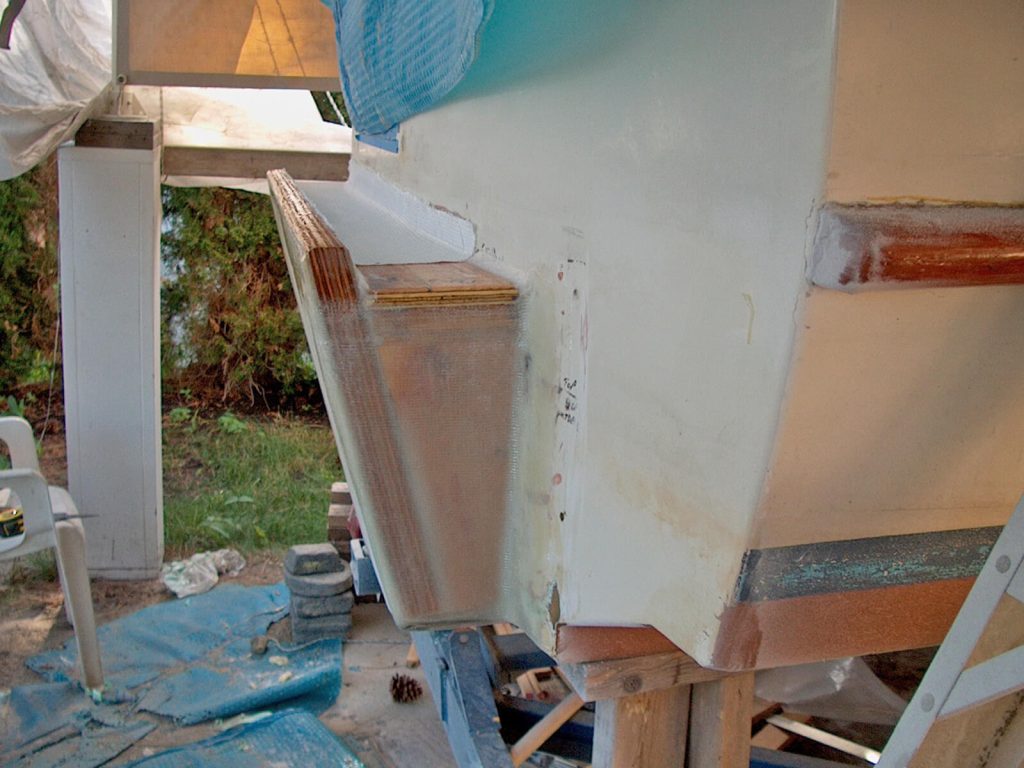
Installing the New Transom Section
While the tabbing cured, I cut and test fit my ¾” plywood filler strips. These would connect the sides and top of the new transom to the original one. The filler strips were intentionally inset from the edge of the new transom section. This space allowed additional reinforcement layers.
It was time to begin the permanent installation of the new transom. I applied a good bed of thickened
epoxy to all the mating surfaces—the hull extensions, transom knees, stringers, filler strips, etc. Once cured, the bond would be strong enough to hold all the pieces in place, so that I could begin reinforcement.
Across the bottom of the new transom section, I used two layers of fiberglass to tab the hull extension/transom joint. Around the remaining perimeter of the new transom section, I applied five layers of fiberglass. Then I added a layer of ¾” plywood to both the sides and the top. This was all then covered by two layers of fiberglass, one layer of carbon fiber, and followed by one layer of fiberglass. One more ¾” plywood piece was added to the top, then a couple more layers of fiberglass completed the layup. This brought all the sides flush with the edge of the new transom section.
To attach the new transom section to the inside of the hull, I applied three layers of fiberglass, a layer of carbon fiber, and then another layer of fiberglass.
The knees were already bonded in place with the initial placement of the new transom section, but they needed reinforcing fabric. I used fiberglass to cover the stringer/knee joint and to tab the knees onto the hull. Though I had used carbon to tab the transom to the hull, I used fiberglass to attach the knees since they had more surface area for a stronger bond.
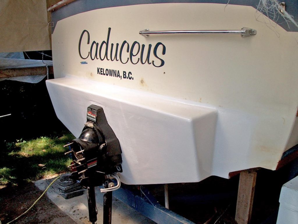
The Swim grid will go on after the fall haul out.
Almost Finished
I gel coated the exterior of the new transom, and it finally felt like the end was in sight. I installed all the engine hardware. Luckily, the engine fit perfectly on the new motor mount pads. I measured correctly. After that, I reconnected everything and installed the brackets for the trim tabs. The swim grid will go on after the fall haul out, but for now, it’s time to get her out on the water again.


