Foam Strip Plank Boatbuilding
Spring 2012

GET STARTED
FREE PRINT & DIGITAL EDITIONS
Spring 2012
BY JOHN LINDAHL
A couple of years ago my son Ian asked me about building an A Class catamaran. Having built several of these in the past and knowing what was now on the market, I came up with a build method that would:
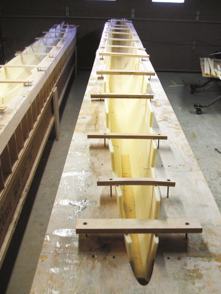
The basic hull build technique is the same as used in strip-plank canoe building. This method allowed us to use an inexpensive but accurate “mold.” We CNC cut a bunch of female building frames that allowed us to build a hull inside these super accurate frames. We cut a frame for every 6″ of hull. I felt this many frames were necessary to keep the hull shape as accurate as possible. Only seven sheets of ½” plywood were cut to create the building frames and frame tops. The strongback was simply two 20′ floor trusses. In the photos you can see I split the hull horizontally. On the next boat I will split it vertically and make the laminating process easier.
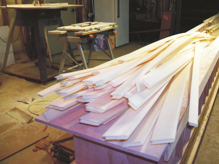
I cut the foam strips into three different widths, so hull shape would not be compromised by a too wide or too narrow strip. These strips were then bead and coved for uniform hull thickness and to ensure fairness. (We don’t like to sand). A 3/4″-thick foam strip was used as a centerline starter on both the deck top and hull bottom. Putting the strips in the hull frames was fun because we could see the hull take form and it only took a couple hours to “lay it up.”
The foam shell needed to be lighted sanded and sheathed in carbon. We sanded the inside first since our frames were female. The excess foam was trimmed flush to our building jig and a shiplap add-on was installed on the deck half building jig. This allowed the inner carbon skin to extend past the join line and form a doubler at the hull joint.
Laminating the inside of the hull was very difficult due to working inside a narrow space, and it was hard to see what I was doing. I complicated this step by laying the carbon on the bias (45-135), which was awkward to work with, but it added hoop strength to the hull. (The outside was done 0-90 for longitudinal strength.) The best method Ian and I came up for laminating the carbon was to lightly wet out the foam, lay in the 50″ wide carbon cloth and then squeegee unthickened WEST SYSTEM epoxy into the fabric.
Once we felt it was wet through, we wet it out again to ensure the fabric was laminated to the skin. After cure we could trim the join line, add bulkheads, chain plate reinforcements, and buildup the rudder gudgeon area. The shiplap add-on was now removed to leave us an inside overlap of carbon. This overlap flap made joining the halves rather easy. All it took was some thickened epoxy and a few simple clamps. We were surprised how stiff each half was since we only had the inside skinned with carbon.

We filled the cloth weave with WEST SYSTEM epoxy thickened with 410 Microlight® filler, spreading this onto the hull with a squeegee and checking for fairness with a batten. After rolling four coats of an epoxy paint primer onto the hull, we did the final fairing. We didn’t prime the areas where beams were to be attached.After the hull halves were joined, we added the dagger board case and the transom. We embedded the tramp hooks into the ¾” thick foam strip on the centerline of the deck. Now the hull could be faired smooth on the outside. Because our foam strips had been cut in widths that corresponded to the hull curvature, the fairing process took only about eight hours per hull. Some fill was needed on a few strip joints and low spots. Carbon was then laminated to the outside of each hull. Again we paid a lot of attention to the amount of epoxy we applied, because excess is weight you don’t need.
  |
  |
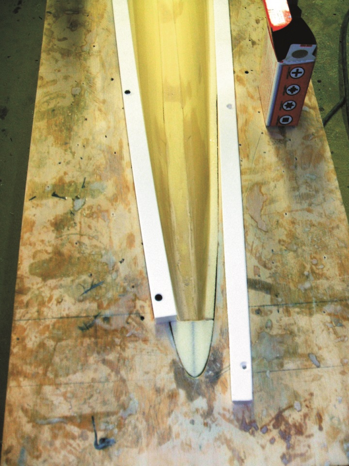
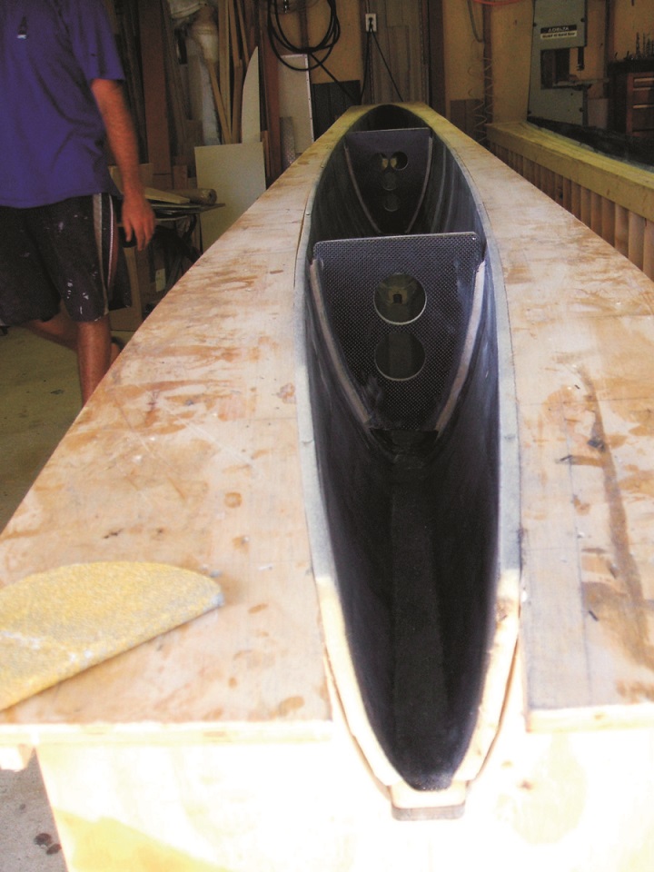
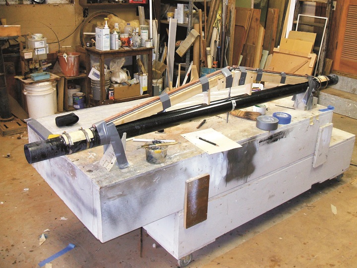
| 5—The hull being hollowed out to prepare for the aft beam to be glued on. |
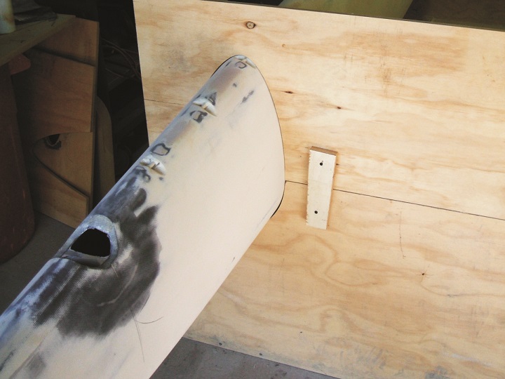
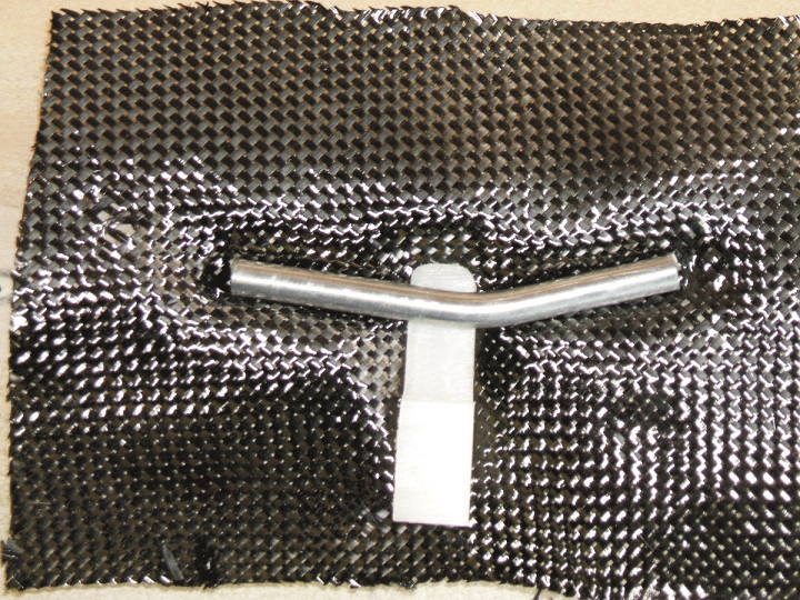
6—Tramp hooks before installation. |
All the boats I’d previously built had bolt-on beams, but this hull shape did not have much area for bolts. Instead we glued the beams on. That decision proved correct as it led to a very stiff platform. Torsional stiffness was only limited by the beams themselves, and they were more than adequate.
Rather than reinvent the wheel, we purchased carbon beams from Ben Hall and then added a carbon dolphin striker to the front beam and a traveler track attachment flat to the rear beam. Installing the beams started with a hull alignment jig that was nothing more than a couple sheets of ply-wood CNC cut to give the seven degree hull cant and to keep the hulls in line and at proper legal width.
  |
  |
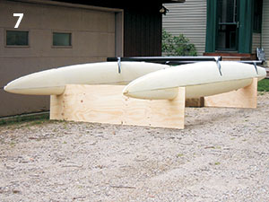
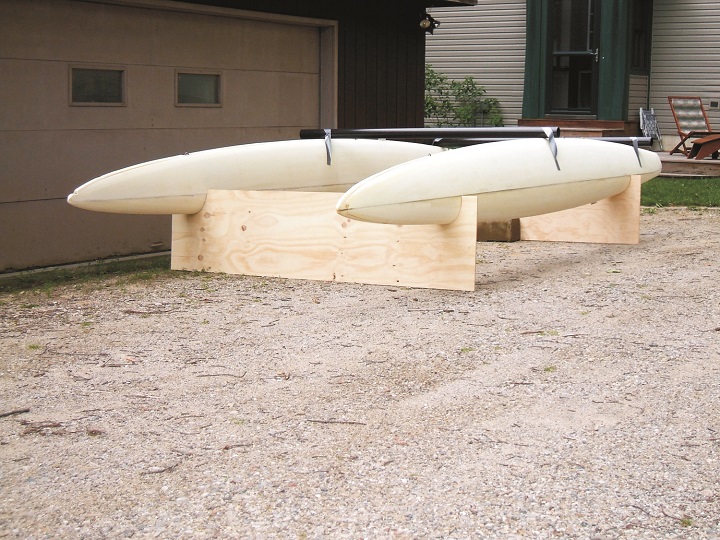
| 7—Hulls sitting in the alignment jig with the beams in their approximate positions. | 8—Carbon beams were purchased from Ben Hall and then a carbon dolphin striker was added to the front beam. |
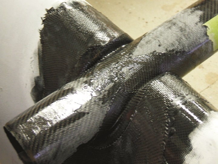
With the hulls fixed in the alignment jig the beams could be locked in place. First we had to hollow out the hulls where the beams would sit. We then laid a wet piece of 5.8 oz carbon into the cutout and set the beam into it. Strips of bias cut cloth were then wrapped into the junction of hull and beam. After cure and minor fairing, unidirectional carbon was wrapped over each beam (in and out) and onto the hull. Carbon was laminated from the inside of the beam onto the hull as well.
Low-Density filler and epoxy were used to fair all four joints. A foam cap sealed the end of each beam. A final wrap of 5.8 oz then went over the whole joint.
  |
 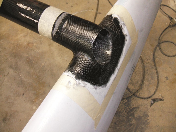 |
| 9, 10—After the hulls were hollowed out where the beams would sit, a wet piece of 5.8 oz carbon was laid into the cutout and the beam was set into it. Strips of bias cut cloth were then wrapped into the junction of hull and beam. After cure and minor fairing, unidirectional carbon was wrapped over each beam and onto the hull. | |
With the beams attached, tramp hooks, gudgeons, and chain plates installed the platform could be finish-primed and sanded. The cost of mold frames and the alignment jig was under $500. We had a male pattern CNC’d for boards and rudders, and then made glass tools for building the actual parts. The foils are an excellent shape, and we kept the board weight under three pounds each. Beams and mast came from Ben Hall. We made the spreaders, mast base/rotator, standing rigging, boom. Local suppliers were used for hardware, rudder heads and paint.
Three boats have been built this way. The first two were 3–5 lb under when weighed at the Worlds. On boat Number 3 we sunk the front beam deeper into the hull and trimmed the beam ends flush with the hull. We also did a better job fairing and used less primer. Number 3 was 15 lb under weight at the Worlds. There have been no structural issues on any boat, so we feel we have a winner. Now it will take a little time to learn how to tune it and sail it faster.
One of the neat things about this building method is that it can be used for a lot more than boatbuilding. This method provides the ability to create whatever you want at a fraction of the cost of building fiberglass molds.
 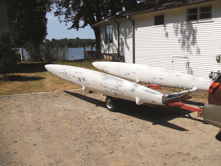 |
11—The faired catamaran upside- down on a trailer. Gluing the beams to the hulls rather than bolting them on resulted in a very stiff platform. |
John Lindahl has been building and racing A Class Catamarans for thirty-five years. Formore info on this building method, available boats, kits and components, contact John (269-650-5900) or Ian (858-688-5450) at Lindahl Composite Design, or e-mail: [email protected].
To see more of Lindahl’s work visit: www.lindahlcompositedesign.weebly.com


