By Jeff Wright — Vice President of Technical Services
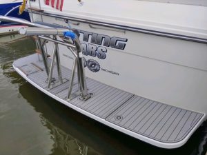
Above: Captain and first mate contemplate ways to free up the swim platform and keep the drinks cold aboard the 1986 242 LS, FUNKTIONAL.
My personal boat is a 1986 Formula 242 LS. With a soft riding deep V hull, good performance, and a small but well-appointed cuddy cabin, it is a great boat for me, my wife, and our dog to use for a whole weekend. One shortcoming, besides not having standing headroom in the cabin, is the built-in cooler located in the cuddy cabin. The cooler had a side door and was styled to look like a refrigerator. This may have looked “cool” in the mid-1980s but was impractical. We couldn’t put ice in the cooler without having the water leak out through the door. For any trip longer than one night, I had to use a standard cooler strapped to the swim platform. This was inconvenient and limited the use of the platform at the beach.
As I investigated the possibility of building a new cooler, I discovered unused space behind the original cooler that I could take advantage of by optimizing my design. Since I was doing this project during the cold Michigan winter, the thought of spending hours measuring and fitting a cooler into the compartment, and making a mess in my cuddy cabin, was not appealing. Thinking back to my work as an engineer at a boatbuilder, I remembered how nice it was to have CAD (Computer-Aided Design) software to model or draw, in three dimensions on a computer screen. Just a decade ago this software was generally expensive and required a fairly high-performance computer. Recently, I discovered that Google® offers a free modeling program called SketchUp. Although SketchUp has some limitations, it was more than powerful enough for my cooler project and ran well on my 8-year-old home PC. And did I mention it’s free?
Special computer skills are not required to use this computer program. Google offers easy-to-follow tutorials. Just give yourself a few hours to learn the commands and you’ll be able to create just about anything on the screen.
Creating the Model
The first step in the project was to remove the existing cooler and measure the inside dimensions of the compartment. With this information, I created a three-dimensional computer model of the compartment that I could use to “build” my cooler on the computer screen. To further optimize the space I removed a few unnecessary wooden parts that held the original cooler.
The Design
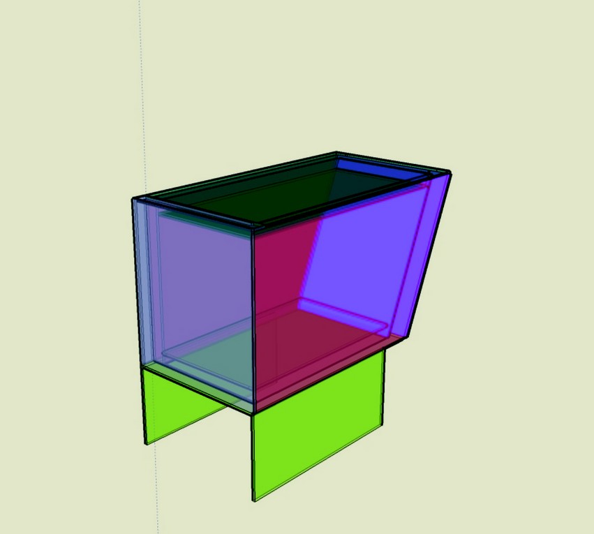
Sitting in my warm house, I considered what cooler dimensions would allow room to access the through-hull drain, enable the cooler to be easily removed, and how well certain food and beverage containers will fit inside. You may get an odd look from your spouse when measuring a half-gallon of milk from the refrigerator. The method of construction I decided on was ¼” plywood on each side of 1″ insulating foam. This combination was a good compromise, maximizing insulation and interior volume.
The outside and inside pieces of plywood on each panel are different sizes. The computer was a great help in deciding how to have all of the pieces join. Another powerful feature of CAD is the ability to measure the clearance between the cooler, hull side, and bulkheads. From the screen to the shop I used the Layer tool in SketchUp when I created the computer model. This allowed me to print out a drawing of each wood piece individually with dimensions. I chose ¼” birch veneered plywood from my local big box lumber yard.


From the Screen to the Shop
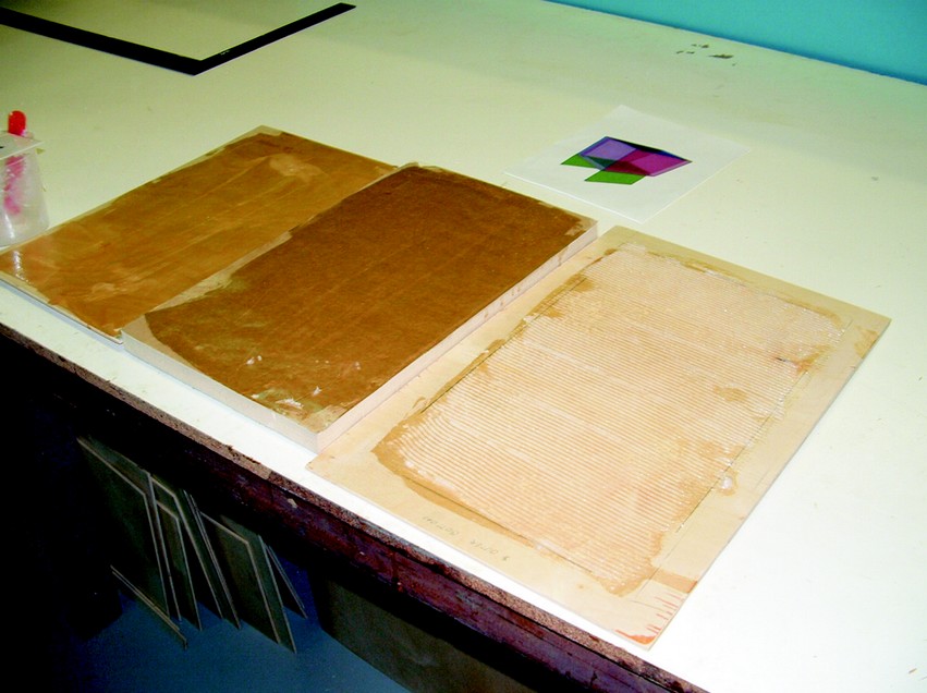
After multiple coats of WEST SYSTEM® Epoxy, the plywood would be durable enough for this application. I cut all of my wood parts, then used them to make patterns for my foam pieces. I chose standard Dow® insulation foam and peeled off its blue plastic film vapor barrier to ensure good adhesion to the aluminum face below. I sanded the side that had a bright aluminum finish lightly with 180-grit sandpaper so I would not actually sand through to the foam.
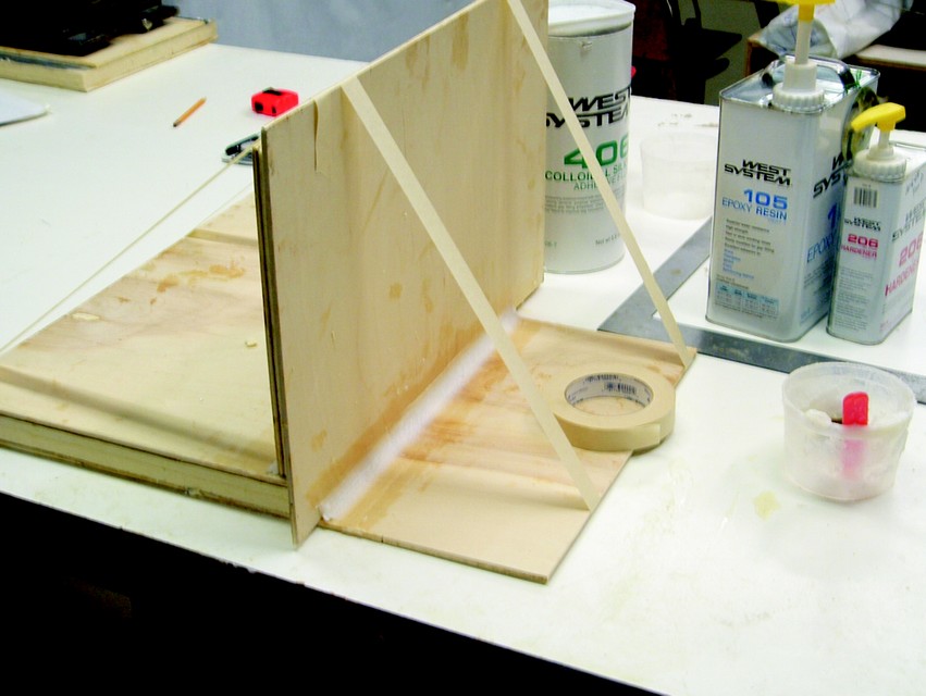
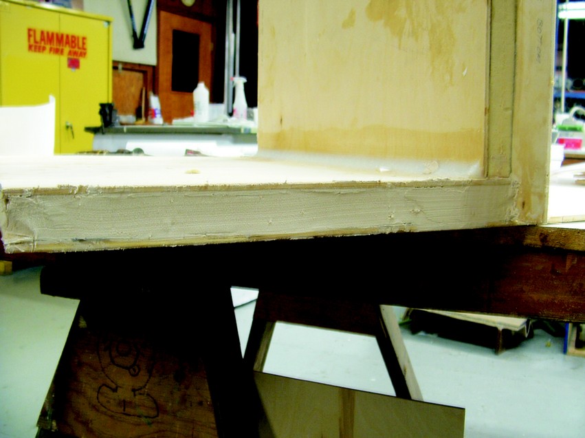
I bonded each panel together by first coating the plywood and foam with a layer of 105 Epoxy Resin® and 206 Slow Hardener® to ensure the surfaces were saturated with epoxy. While the initial coat of epoxy was still uncured, I used a notched trowel to apply a layer of 105 Resin and 206 Slow Hardener thickened with 406 Colloidal Silica. I then placed both sheets of plywood onto the foam and used simple weights to clamp the pieces together. The plywood had warped while sitting in the shop so the weight was required to create a flat panel. If the panel had an exposed edge, I removed the foam from between the plywood to a depth of about ½” and then filled with 105 Resin/206 Hardener and 410 Microlight®.

Assembling the Cooler
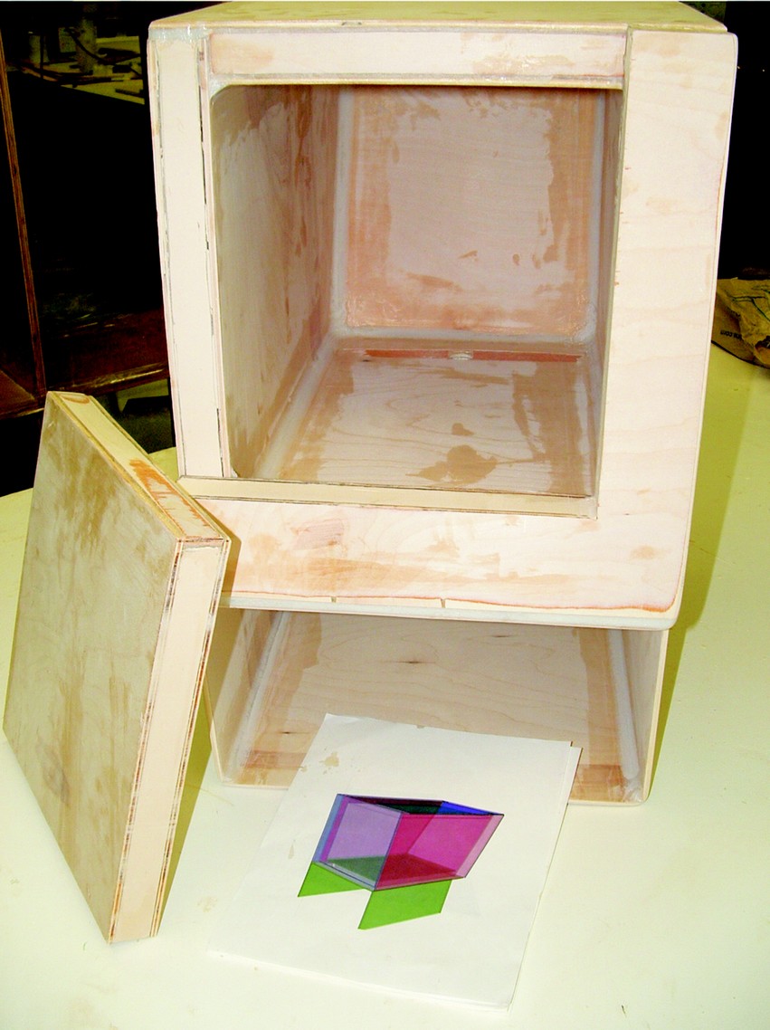
After the panels were all glued together it was time to create the box which would become the cooler. Since I don’t have cabinetmaker woodworking skills, using fillets of thickened epoxy to bond the panels made up nicely for joints that didn’t fit as perfectly as I had hoped. This was also good time to work on the door. I made a very simple cut out of the front panel and then used flat hinges for attachment. Unsure if I would need a gasket, I placed small pieces of plywood inside the opening to create a landing for the door to seat against in case I wanted to add gasket material later. To prevent liquids from spilling out, the opening doesn’t go all the way to the bottom.
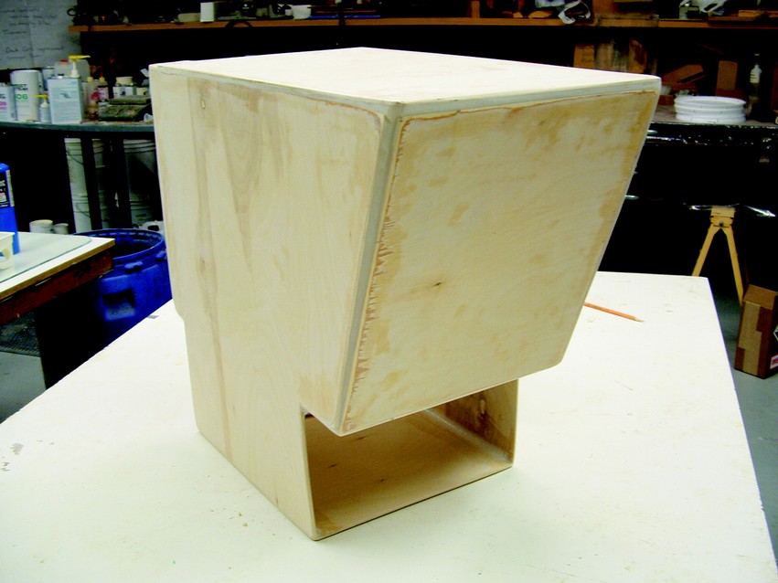
When all the panels were bonded together, I coated the inside with several heavy coats of 105/206 and 501 White Pigment. Since the inside will be very wet and containers will bang around inside, a coat of pigmented epoxy was ideal. I then coated the entire exterior. I waited until it was assembled because I knew I would have to sand the outside to improve the appearance at the joints as well as imperfections in the plywood. After the epoxy cured, I painted the exterior with a white oil-based paint, then installed the hardware.
Fastener Bonding
To hold the cooler down in the cabin I bonded ¼” nuts in the floor. I accomplished this by drilling oversized holes and then threading the nuts onto waxed ¼” bolts. After the epoxy cured, I had a stainless steel nut glued into the floor that could easily bolt the cooler to, repeatedly.
Installing the Cooler
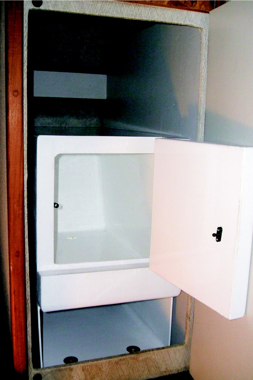
Once I had the cooler painted and the fasteners in the floor, I placed the cooler and installed the bolts. Although I had accounted for the dimensions of this compartment accurately and the cooler fit great, I did not model the wet bar on the opposite side of the cabin which made it difficult to turn the cooler 90 degrees after carrying it through the companionway. By tilting the cooler upward I could put it in place easily. I was very relieved that my oversight did not force me to redesign the cooler.
New Cooler, Old Boat
The new cooler I designed in Sketchup lets the ice water drain overboard and provides a whole new storage area above the cooler. In rough water, the bolts hold it in place without any problems. This was a great project that made a small improvement in an older boat which is just the type of thing that keeps “two foot-itis” (the desire to buy a boat two feet longer) away for another boating season.


