By Alvin Gall
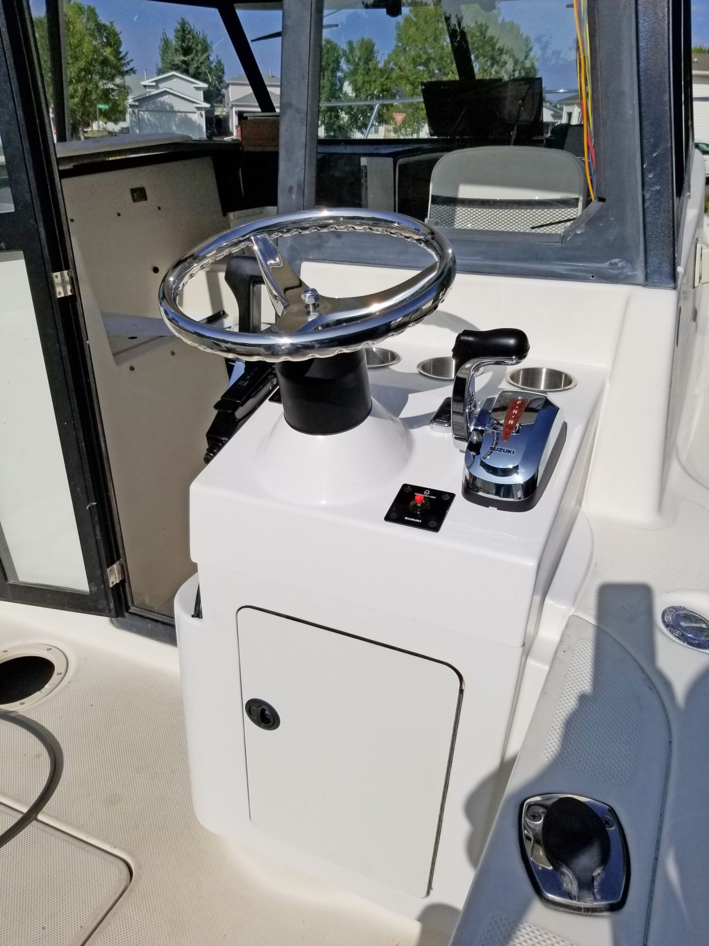
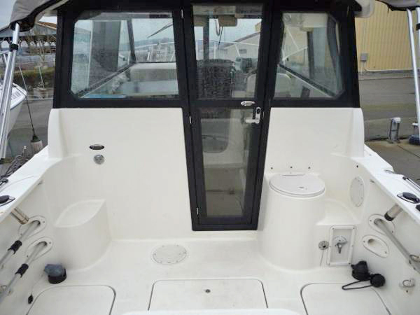
From past fishing experiences, I’ve learned that quick changes in speed and direction are often required when retrieving a hooked fish. Having a control station on the fishing deck of our Trophy 2359 would make for a more enjoyable fishing experience. Since we’ve been underutilizing our bait well, we chose to sacrifice it and built a new rear station in its place.
In our new rear station, we needed to have controls for our primary motor, hydraulic steering and 20 hp auxiliary motor. Our primary motor shifter and throttle up front in the cabin are electronically controlled, so adding a second set of controls nearer the stern was just a matter of ordering a few parts and connecting them. The same for the hydraulic steering. The 20 hp auxiliary motor, however, is primarily used for trolling, so we decided its only set of controls could be at the rear station.
Not having undertaken a project like this before, there was a lot of information to ramp up on. I read related sections of The Gougeon Brothers on Boat Construction, I read through projects in Epoxyworks, searched the internet for similar projects, and watched online videos.
Building a Plug
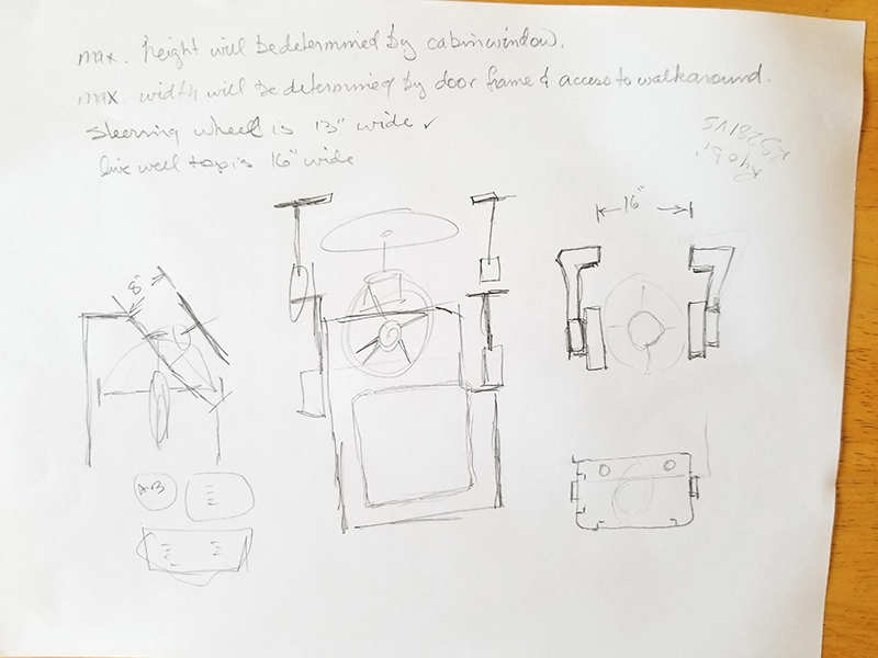
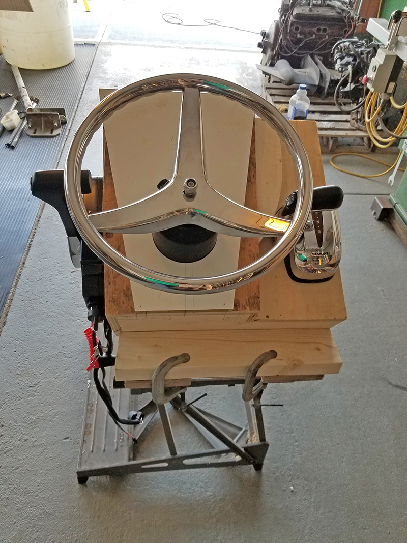
Armed with my knowledge, I sketched plans and revised again, and again. In my fabrication facility (aka, my garage), I made a mock-up of the dash out of scraps of wood to ensure the wheel, throttle, and shift levers were spaced appropriately. Using an oscillating saw, I cut the live bait well out of the boat about 4″ above the deck to allow for a toe kick and 2″ from the rear bulkhead to leave a flange for attaching the rear station to the hull.
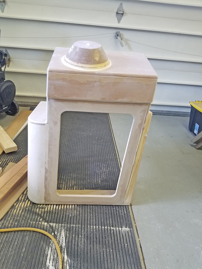
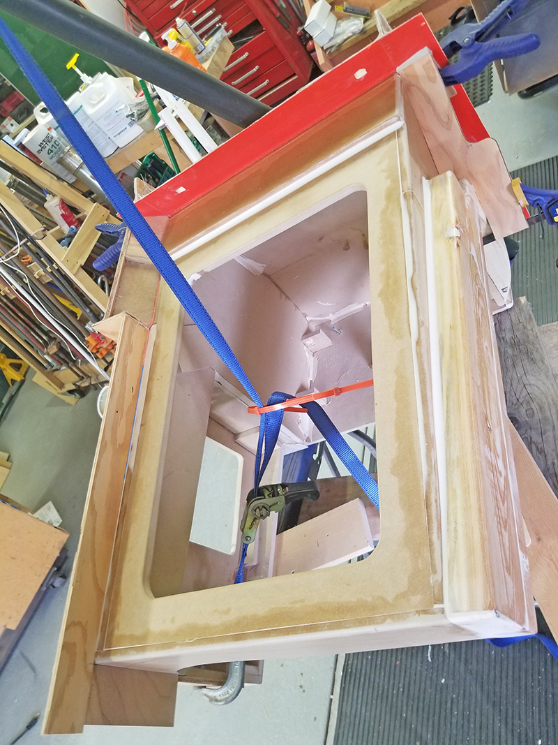
I cut corrugated cardboard templates to follow the curved contours of the inside of the hull, the inside edge of the gunwale, and the back of the cabin bulkhead. Once I had a perfect fit, I used these templates to cut a plug out of ¾” MDF. I assembled the plug, test fit, and adjusted it until the plug fit perfectly in place.
The cracks and joinery gaps in the plug were filled with WEST SYSTEM® 105 Epoxy Resin® and 206 Slow Hardener® thickened with 410 Microlight® Fairing Filler. I chose 410 Microlight® Fairing Filler so that the fairing compound could be easily sanded with a finer grit sandpaper. This way I would be less likely to abrade the soft MDF plug. Then I applied multiple layers of wax to the plug.
Laminating the Molds
With the plug finished and prepped, it was time to laminate the mold of the plug. The mold was made in four pieces, one at a time. I made sure to mold registration keys into the parting molds using putty. This ensured they would “lock” together in the correct place once they came off the plug. I applied the epoxy compatible in-mold coating to the plug following the manufacturer’s instruction. I applied layers of 6 oz. fiberglass cloth saturated with WEST SYSTEM 105 Epoxy Resin and 206 Slow Hardener.
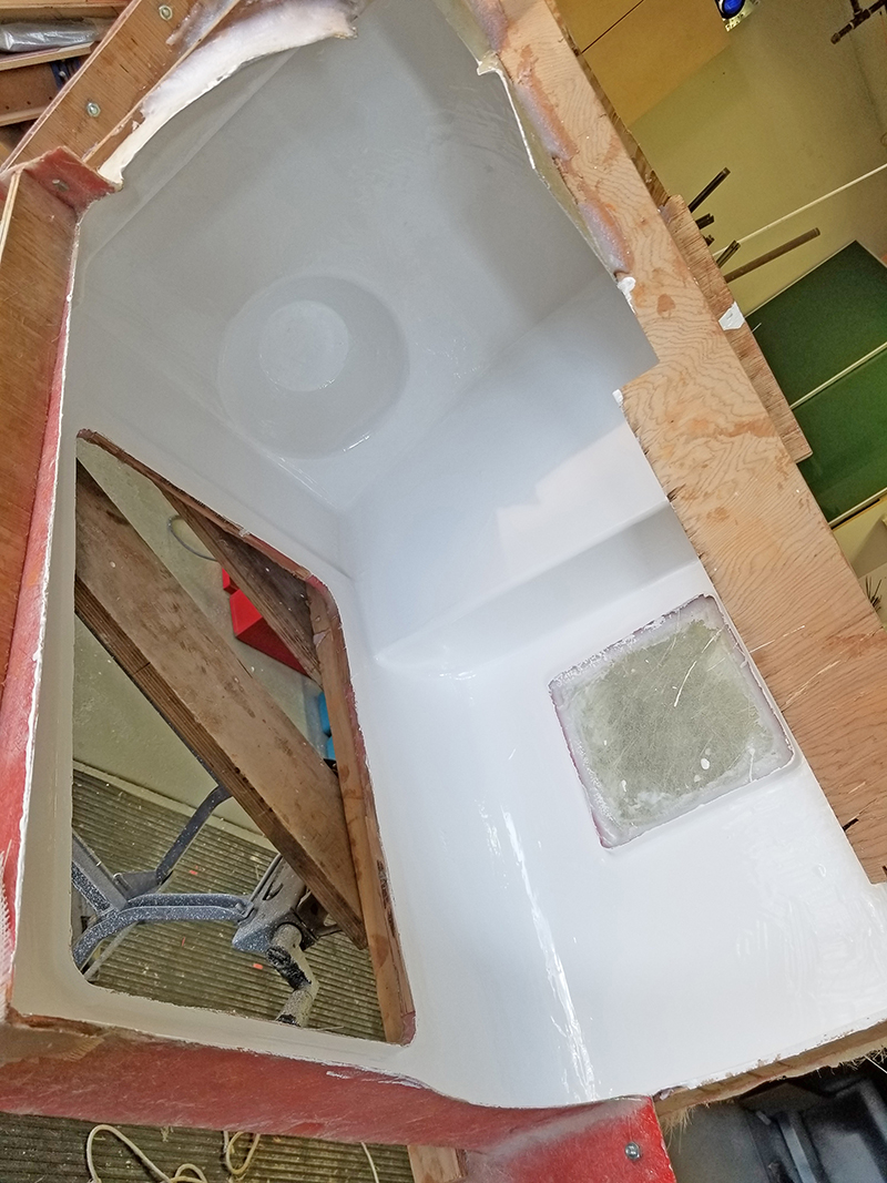
The edges of the molds, and the larger flat areas of the mold, were stiffened with scraps of plywood placed on edge 90 degrees to the surface. They were attached with the same 105/206 epoxy, then I added a fillet of epoxy thickened with WEST SYSTEM 403 Microfiber Filler for additional strength.
After the four pieces were finished, I took off the plug and noticed a few tiny bubbles in the mold surface. I assume these were from my brushing technique or irregular gelcoat thickness. I filled those with epoxy thickened with 410 Microlight Fairing Filler and sanded them smooth. Then I waxed, and waxed, and waxed the inside of the mold.
Casting the Parts
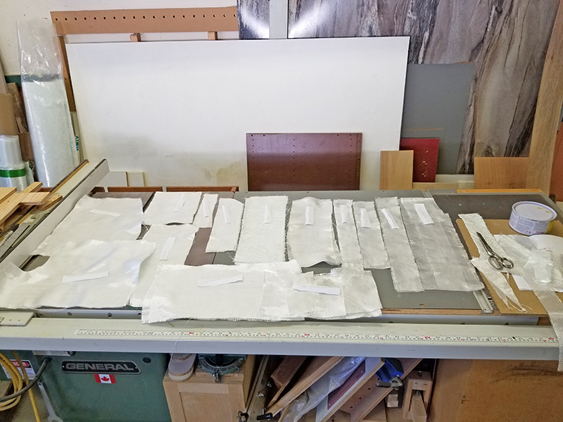
In preparation for laminating the rear station, I precut 6 oz. biaxial cloth and 24 oz. roving into shapes that fit the inside areas of the mold and some pieces of ½” marine grade plywood. The plywood I used for stiffening the larger flat panels and for reinforcing the areas where hardware and attachments were planned. I laid them out in the order of use.
I brushed on the in-mold coating. Then I laid in the overlapping layers of 6 oz. cloth saturated with WEST SYSTEM 105 Epoxy Resin and 206 Slow Hardener. I rolled out the bubbles and let the epoxy get tacky. Then I laid in the slightly heavier layer of fiberglass cloth saturatedwith epoxy and rolled out the bubbles. While the second layer was still wet, I wet one side of the ½” plywood stiffeners with WEST SYSTEM 105 Epoxy Resin and 206 Slow Hardener slightly thickened with 403 Microfiber Filler. I placed the wet sides in the hardware attachment
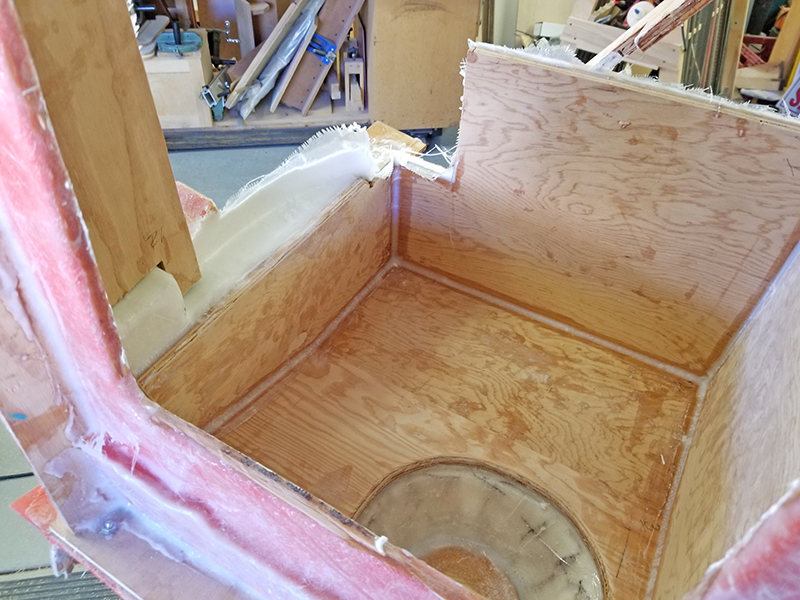
areas of the mold. Then I coated the exposed side of the marine plywood with unthickened 105 and 206. Once that was tacky, I added a fillet to the edges of the plywood using epoxy heavily thickened with WEST SYSTEM 403 Microfiber Filler. Again, I waited for it to get tacky. The final two layers of epoxy-saturated 6 oz. fiberglass cloth were laid over the entire tacky interior area and left to cure.
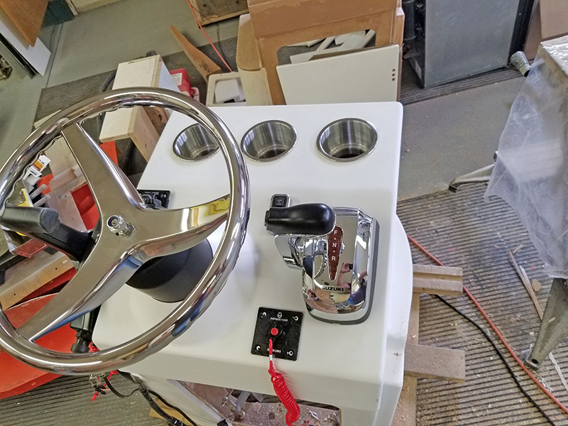
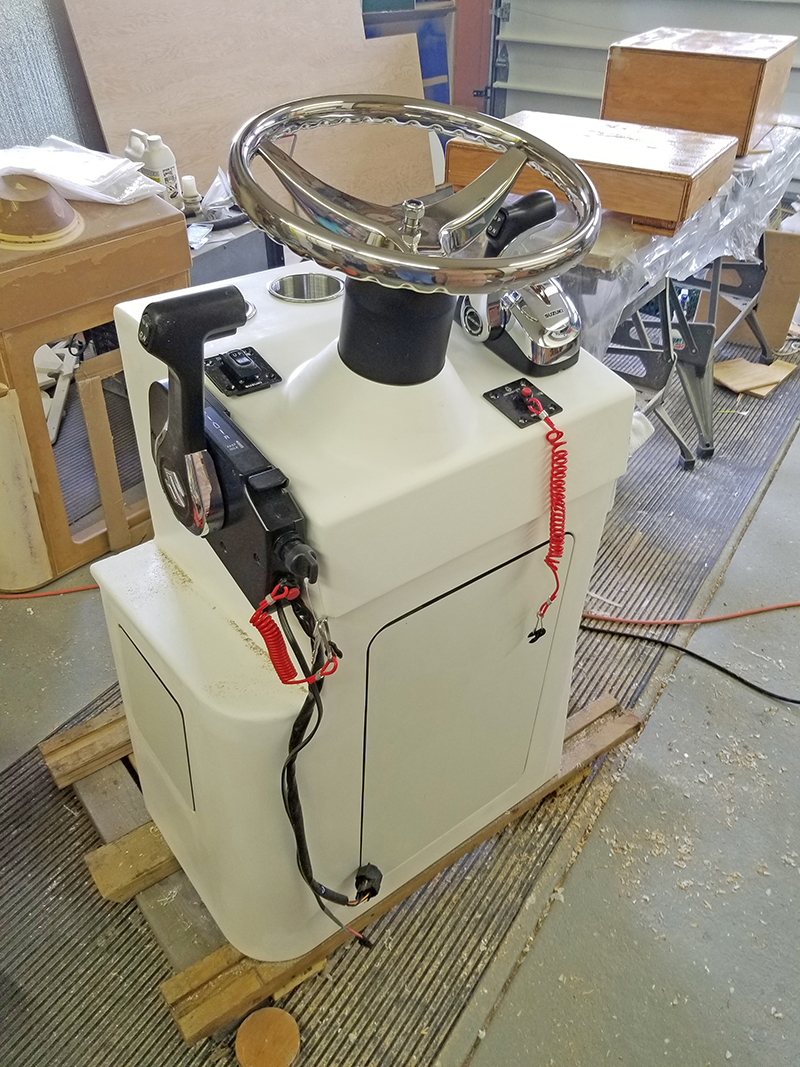
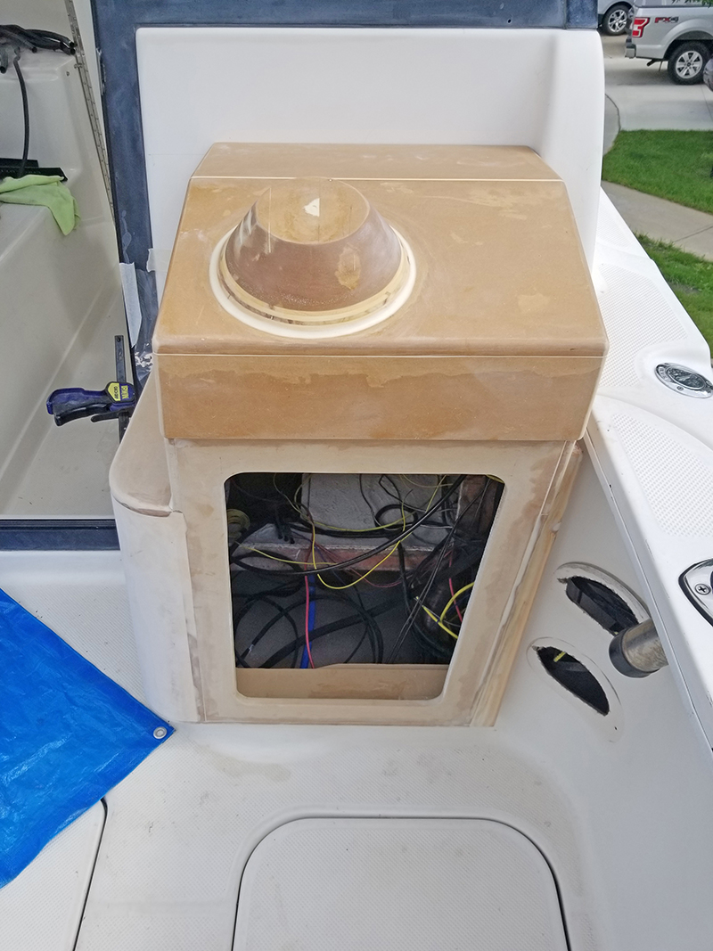
When I removed the part from the mold, I found that small areas of the gelcoat stuck to the mold on two of the round outside corners. I patched those blemishes and sanded smooth. Then I polished and waxed the final product. Measuring twice, I cut holes for beverage containers, drilled holes for the steering wheel, for the screws and cables of the control levers, and for the
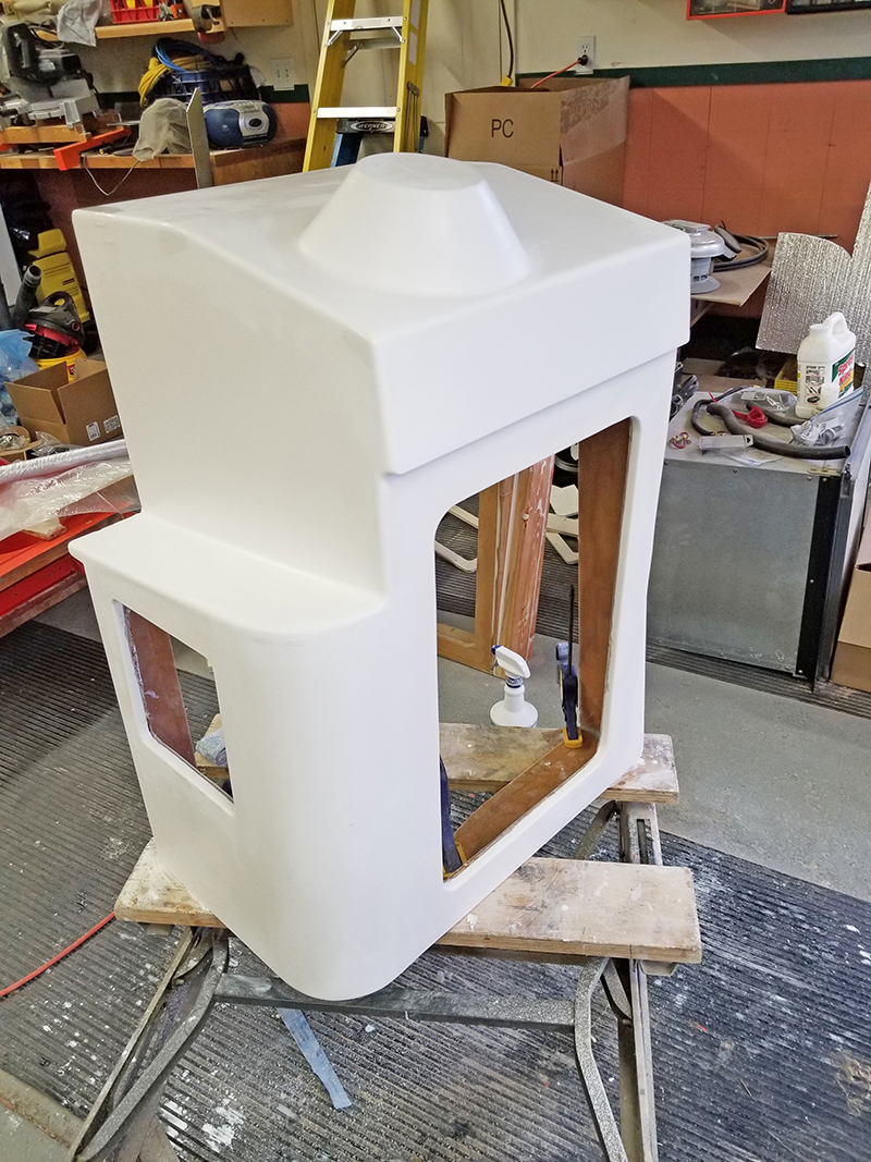
switches for both the primary and “kicker” motors. I made doors for the battery switch and the cabinet from an epoxy laminate. To connect the steering station to the boat I used bolts and screws through the bulkhead, and protruding parts of the original bait well. Any holes that cut through my reinforcing plywood got a coat of neat epoxy to seal the wood. Then I applied a caulk fillet at the joints.
I learned a lot, and I am happy with how my project turned out from both the functional and aesthetic aspects. Research, planning, courage, determination, attention to detail, and the platform of WEST SYSTEM products are all you need to create pretty much anything.